
A solar inverter factory power cable supplier should be evaluated through tested power-electronics output. Assembly can grow quickly, but thermal burn-in, cooling and grid-simulation benches determine how many inverters are released.
The strongest buying process compares suppliers on test-range evidence, route separation and records that remain useful when power ratings or grid profiles change.
This guide uses a scorecard, diagnostic symptoms and an owner playbook.
A buyer scorecard for inverter test infrastructure
Score evidence that connects the cable offer with the approved product range.
| Criterion | Question | Evidence to request |
|---|---|---|
| Rating coverage | Are typical and maximum inverter ratings stated? | Product and test envelope |
| Burn-in capacity | Are duration and simultaneous racks visible? | Occupancy and cooling map |
| Grid-test scope | Are simulators, loads and instruments included? | Bench dependency list |
| Route separation | Are electronics, hot and heavy-test areas distinct? | Marked route assumptions |
| Handover | Can records support new ratings or tests? | Permanent identities and revisions |
The scorecard makes technical completeness part of the commercial decision.
The release path runs from clean electronics to grid simulation
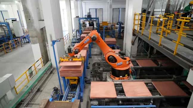
A useful solar inverter factory power cable supplier begins by mapping power-module preparation, control-board assembly, cabinet integration, functional checks, thermal burn-in, grid simulation, inspection and packing. The schedule should connect every important cable group with production flow, quality or final release before suppliers are compared.
An inverter assembly line cable may support component, cabinet and control workstations that change with product architecture. Stable cell and family names protect record value.
A solar inverter burn-in cable and inverter grid test bench cable need the approved power range, duration, cooling, instruments and simultaneous test assumptions.
Symptoms that point to the real inverter test constraint
Use production data before adding more assembly or test equipment.
Symptom: Cabinets wait before burn-in
Likely dependency: rack occupancy or room cooling is insufficient Check: Measure duration, simultaneous load and heat rejection.
Symptom: Burn-in passes but release is slow
Likely dependency: grid simulation or final instruments are limiting Check: Check bench cycle and product changeover.
Symptom: Several benches stop together
Likely dependency: cooling, controls or distribution is shared Check: Map every served bay and standby arrangement.
Symptom: New ratings require temporary wiring
Likely dependency: permanent bay ranges are not documented Check: Define approved connection and test envelopes.
The symptom with the largest queue should guide the next cable investment.
Scenario: larger string inverters overload thermal testing
Situation: A manufacturer introduces a higher-power inverter platform using existing cabinet assembly cells.
Finding: Assembly can build the units, but burn-in heat rejection and grid-test occupancy were planned for smaller ratings.
Decision: The buyer separates normal and maximum test duty and adds cooling, bench and instrument circuits to the expansion scope.
Expected result: The project is measured by signed test reports rather than assembled cabinets.
Questions that expose an incomplete inverter quotation
Each answer should be supported by an approved factory or product input.
What rating range will each bay serve?
State typical, maximum and future power levels.
How long is thermal burn-in?
Provide duration, simultaneous units and room cooling.
Which grid profiles are tested?
List simulator, load and instrument dependencies without asking the cable supplier to define the test.
Where are clean and high-power routes separated?
Mark electronics, assembly, hot and test spaces.
What evidence is handed over?
Agree labels, cable tests, bay identities and final revisions.
Clear answers support accurate pricing and future test-bay changes.
Choose the inverter capacity project by release impact
Select the branch supported by current factory data.
Assembly is limiting
Add cells only after confirming burn-in and grid-test margins.
Burn-in is limiting
Expand racks, cooling and power groups using the approved thermal profile.
Grid testing is limiting
Review simulator, loads, instruments and station occupancy.
New ratings are limiting flexibility
Create range-based permanent bays and documented route capacity.
The cable package should remove the measured constraint and preserve the next product range.
Who owns each inverter factory input?
Assign ownership before suppliers price the project.
| Work stage | Primary owner | Required output |
|---|---|---|
| Product rating and tests | Product engineering | Approved rating, burn-in and grid-test envelope |
| Factory capacity | Production engineering | Units, duration and simultaneous bay use |
| Routes and cooling | Plant engineering | Zone map and shared-system dependencies |
| Cable and delivery | Electrical and construction | Schedule, lengths, installation groups and labels |
| Handover evidence | Quality and maintenance | Tests, records and revision ownership |
A complete owner map prevents assumptions from moving between the product and factory teams.
RFQ details for inverter burn-in and grid testing
The supplier needs approved rating, occupancy and route information to understand the release task.
- System voltage and frequency
- Load or cable schedule
- Motor ratings and starting method
- Route length and installation method
- Actual wet, dusty, hot, outdoor or mechanical conditions
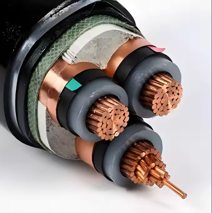
- Required conductor, insulation, sheath and armor details
- Destination, delivery stages and required records
- inverter rating and cooling range
- assembly-cell and electronics layout
- burn-in duration and simultaneous units
- grid simulator, loads and instruments
- test-bay routes, labels and records
For solar inverter factory projects, references such as IEC 60502, IEC 60228 and IEC 60332 can help both sides use consistent terminology. They do not replace the approved specification or the buyer's responsibility to confirm the design.
How JINCHUAN Cable supports solar inverter factory decisions
For power-electronics manufacturers, renewable-energy engineers and factory planners evaluating the solar inverter factory power cable supplier, JINCHUAN Cable can review assembly, burn-in and grid-test cable groups against the buyer's approved power ranges and route conditions.
The proposal can clarify construction, identification, delivery and evidence while product qualification and final protection remain with responsible specialists.
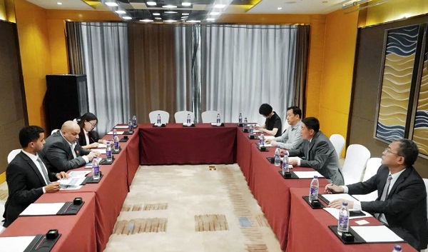
Buyers can review JINCHUAN Cable products and learn more about the JINCHUAN Cable company. Share the project purpose, critical loads, route conditions, quantities, destination and expected records to create a stronger basis for technical and commercial comparison.
Send the rating and test-capacity map to obtain a quotation tied to released solar inverters and future grid requirements.
FAQ
What should buyers expect from a solar inverter factory power cable supplier?
Buyers should expect the proposal to connect cable construction with power-rating range, clean assembly, burn-in occupancy, cooling, grid-test benches and product evidence, not merely repeat conductor sizes from a schedule.
Which part of the solar inverter factory should be mapped first?
Start with power-module preparation, control-board assembly, cabinet integration, functional checks, thermal burn-in, grid simulation, inspection and packing. This shows which supporting loads can interrupt more than one production stage.
How should quotations for the solar inverter factory be compared?
Compare the stated route assumptions, operating duty, included records, delivery grouping and exclusions beside price. That exposes scope differences before approval.
Which route conditions matter in a solar inverter factory?
The inquiry should distinguish electronics rooms, cabinet assembly, heated burn-in areas, cooling systems, instrument labs, grid simulators and loading spaces. Broad labels such as indoor or industrial are rarely precise enough for a useful review.
What hidden risk deserves attention in this project?
A common hidden risk is adding assembly cells while burn-in, cooling or grid-test occupancy remains the release bottleneck. Its production consequence may be greater than the connected load suggests.
Should future changes be discussed before ordering?
Yes. higher inverter ratings, new grid-code test profiles, liquid cooling and additional test bays can affect route capacity, circuit names, distribution space and the value of today's approval records.
Which records help after installation?
Useful records include product-family and bay identities, rating envelopes, cooling dependencies, test routes and final revisions. They help receiving, installation and maintenance teams connect each cable with its purpose.
Which technical references may support the discussion?
IEC 60502, IEC 60228 and IEC 60332 may provide common terminology, while the approved project specification remains the final design basis.
What should be sent with the first RFQ?
Send the cable or load schedule plus project details such as inverter rating and cooling range, assembly-cell and electronics layout, burn-in duration and simultaneous units, grid simulator, loads and instruments, test-bay routes, labels and records. Clear inputs allow suppliers to identify assumptions instead of guessing.
How can JINCHUAN Cable support the solar inverter factory?
JINCHUAN Cable can review the schedule, routes, operating conditions, quantities and required records against the result the buyer needs to protect: clean assembly, stable thermal burn-in, accurate grid simulation and traceable inverter release.