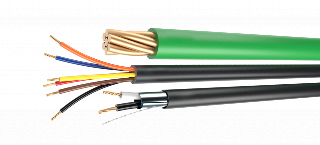

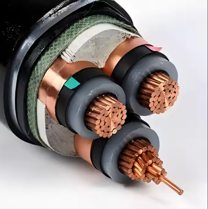
A gland can look tight, an armor can appear intact and a green-yellow lead can be present, yet the intended protective path may still be open at an interface. A cable earthing continuity test turns those visible details into measured evidence, provided the team defines exactly where the test begins and ends.
This is not a request for one universal resistance number. Conductor arrangement, bonding design, parallel paths, cable length, connections and the approved protection strategy all affect what the project authority expects. The useful procurement task is to preserve interfaces and records so the qualified commissioning team can test the designed path without guesswork.
The discussion below begins at the test boundary, moves through hardware and measurement, and finishes with exception control. It is intended for buyers who need traceable cable and accessory information, not for replacing the project's electrical safety design.
Define the Path Before Connecting the Instrument
A continuity result has meaning only when every included component and possible parallel route is named.
| Boundary element | Question to resolve | Record to retain |
|---|---|---|
| Test origin | Is the lead connected to an earth bar, enclosure, gland, screen wire or armor termination? | Marked drawing and photograph with identity |
| Cable section | Which length, joint and termination lie inside the measurement? | Cable register, joint number and endpoints |
| Return path | Is a dedicated conductor used, or can structure and parallel bonds influence the reading? | Test connection sketch and isolation state |
| Equipment interface | Are paint, coatings, washers, adapters or removable plates part of the path? | Approved assembly detail and inspection record |
| Operating state | What is isolated, disconnected or left bonded during the check? | Permit, method and switching condition |
| Acceptance basis | Who sets the limit and evaluates uncertainty? | Approved commissioning procedure and signature |
Write the boundary beside the reading. A bare value copied into a spreadsheet cannot prove which protective path was actually measured.
Write each cable earthing continuity test boundary beside its reading so reviewers know which interfaces were included.
The Painted Gland Plate That Passed a Visual Check
Situation: A row of armored feeders is terminated through a removable steel plate. The glands are tight and neatly labeled, but continuity readings vary widely between otherwise similar circuits.
Finding: The plate coating and inconsistent bonding hardware interrupt the intended metal-to-metal interface. Some readings also include an accidental parallel path through equipment structure, making spot results appear better than the direct gland connection.
Decision: The team stops release, confirms the approved bonding detail, prepares the interfaces correctly, controls parallel paths according to the test method and repeats each measurement with permanent cable identities.
Result: The final record distinguishes the designed bond from incidental structure, and the corrected assembly is inspectable during later maintenance instead of relying on appearance.
A cable earthing continuity test should follow hardware inspection because poor preparation can dominate a low-resistance result.
Inspect the Hardware Before Chasing Milliohms
Many failed readings begin with an assembly problem that should be visible before the meter is attached.
Armor preparation
Check that wires or tape are prepared to the approved gland or termination method without missing, folded or damaged elements. Confirm the correct accessory range for the finished cable diameter.
Gland and enclosure interface
Review thread engagement, locknuts, earth tags, serrated washers, coatings, reducers and plate thickness against the released detail. Tightness alone does not prove a conductive interface.
Screen or drain connection
Identify the designed bonding point, conductor route, lug, fastener and insulation from adjacent metalwork. Do not assume the screen follows the same path as armor.
Joint continuity
Where a joint lies inside the boundary, verify the accessory construction, bond connection, identification and installation record before interpreting the end-to-end result.
Instrument selection for a cable earthing continuity test must suit the expected range and the approved field procedure.
Use an Instrument Suited to the Expected Result
A cable earthing continuity test may involve very low resistance, so ordinary lead resistance and contact condition can influence the displayed value. The approved method should state the instrument type, lead arrangement, range, zero or compensation procedure and calibration status. Record raw readings rather than only a pass label.
Test current and connection stability should follow the project procedure and equipment instructions. The operator should wait for a stable result, note fluctuating contacts and avoid scraping or clamping in a way that creates an artificial connection unavailable in normal service. Qualified personnel must control isolation and electrical safety throughout the work.
Temperature, length and conductor material may matter when the result is compared with a predicted path. The commissioning engineer decides which corrections or uncertainty are relevant; the field record supplies the facts needed to reproduce that decision.
Parallel bonds can change a cable earthing continuity test result without proving the intended direct connection.
Parallel Paths Can Make a Weak Bond Look Healthy
Metal structures, protective conductors, screens and connected equipment can create more than one return route during measurement.
- Draw the intended protective path and list every known parallel bond before testing.
- State which connections remain in service and which are temporarily isolated under the approved method.
- Compare direct component checks with end-to-end results when the procedure requires fault localization.
- Restore every temporary disconnection, then verify restoration and close the permit record.
- Never remove a safety connection merely to improve diagnostic clarity unless the authorized procedure and responsible person permit it.
The goal is not to obtain the lowest possible number. It is to prove the path that the protection design intends to use.
Close every failed cable earthing continuity test with preserved raw data, cause, corrective action and authorized release.
Continuity Evidence by Project Stage
Different teams see different parts of the bond. A planned evidence chain prevents critical interfaces from disappearing behind covers or backfill.
| Stage | Useful check | Owner-facing output |
|---|---|---|
| Cable and accessory review | Construction, armor or screen, gland range and bonding components | Approved datasheets and interface schedule |
| Receiving | Cable identity, drum condition, accessory quantities and certificates | Receiving report linked to item numbers |
| Installation | Preparation, hardware, torque where specified and hidden interfaces | Inspection checklist with photos and installer |
| Commissioning | Defined-boundary readings, instrument data and exceptions | Signed test sheets plus raw values |
| Handover | As-built path, final connection state and maintenance access | Searchable cable, joint and equipment register |
A factory certificate supports product identity, but the installed bond still needs project-specific inspection and commissioning evidence.
When One Reading Differs From Its Neighbors
Situation: Four comparable feeders share the same construction and approximate length, but one end-to-end result is noticeably higher during commissioning.
Finding: Averages would hide the outlier. The cable identity, joint history and connection details show that the affected feeder passed through a replaced gland and a separately installed bond lead.
Decision: The reviewer keeps individual results, divides the path into approved diagnostic sections and inspects the changed interfaces rather than immediately condemning the cable conductor.
Result: A loose bond-lead termination is corrected and retested. The exception record explains the cause, action and final release without misattributing the problem to the manufactured cable.
Disposition Rules for an Unexpected Result
Exception handling should preserve safety, original data and responsibility while the cause is narrowed.
Confirm identity and setup
Recheck endpoints, cable number, instrument, leads, range, connection condition and approved isolation state before changing the installation.
Repeat without erasing
Retain the first result, then repeat under the stated method. A second pass should not overwrite evidence of an intermittent or setup-related issue.
Localize the path
Use authorized intermediate checks and inspection to separate gland, bond lead, joint, armor, screen and equipment-interface contributions.
Release through the named authority
Document finding, corrective action, final reading, restored configuration and the person responsible for acceptance or further engineering review.
Commercial Scope That Belongs in the Accessory Package
Continuity problems become expensive when the cable, gland, lug, bond lead and enclosure interface are bought as unrelated items.
- Match glands and termination components to the actual conductor, insulation, sheath, armor or screen construction and finished dimensions.
- State whether earth tags, locknuts, washers, reducers, shrouds, bond leads, lugs and fasteners are included or supplied by others.
- Define sample fitting or dimensional approval where enclosure space, thread form or plate thickness is uncertain.
- Name installation evidence, test sheets, witness points and dossier format before production and site mobilization.
- Allocate compatible spare accessories by cable item instead of providing an untraceable mixed box.
A complete interface price is easier to compare than a low cable price followed by urgent accessory substitutions at site.
Handover the Bond as a Maintainable Asset
The final file should allow a technician to locate each bond, understand its normal connection state and repeat the cable earthing continuity test after maintenance. Include feeder, phase where relevant, cable, gland, joint, equipment, drawing and test-sheet identifiers in one searchable index.
Retain raw readings, instrument details, inspection photographs, exceptions, repaired interfaces and approval signatures. Where a parallel path affected the method, explain its condition plainly so a later team does not compare unlike measurements.
Changes to glands, removable plates, joints or bonding leads should trigger an update. Continuity is not a one-time document property; it depends on physical interfaces that can be disturbed during equipment replacement and enclosure work.
Build the Bonding and Test Scope Into the RFQ
Give suppliers the approved cable construction and interface facts needed to quote compatible hardware and traceable product evidence.
- system and protection basis issued by the responsible engineer
- cable schedule with armor, screen and protective conductor details
- gland, joint, termination and enclosure interface drawings
- thread forms, plate material, thickness, coatings and access
- bond leads, lugs, washers, fasteners and torque requirements
- test boundaries, parallel-path controls and acceptance procedure
- factory, receiving, installation and commissioning records
- spares, labels, dossier index and change-control responsibilities
Technical references such as IEC 60502, IEC 60228 and IEC 60332 can align cable construction and test terminology. The approved project specification, applicable local rules and qualified design authority still govern the final system decision.
JINCHUAN Cable Support for bonded cable systems and protective paths
JINCHUAN Cable can clarify ordered cable construction, armor or screen details, finished dimensions, drum identity and agreed factory evidence. Those inputs help the buyer coordinate glands, joints and bonding hardware with the project's approved protective-path design.
Use the JINCHUAN Cable product overview and company information as a starting point, then send the cable and accessory schedule for an item-specific technical and commercial response.
Before release, make the test boundary, accessory interfaces, parallel-path condition and acceptance owner explicit. A visible bond is not complete evidence until the intended path is measured and recorded.
FAQ
What does a cable earthing continuity test prove?
It verifies electrical continuity across the defined protective path under the stated test condition. The boundary and acceptance basis must accompany the reading.
Can a visual inspection replace continuity measurement?
No. Inspection can identify poor preparation or missing hardware, but it cannot by itself quantify the electrical path required by the commissioning procedure.
Why should the test origin and endpoint be written down?
Without endpoints, a result cannot show which glands, joints, armor sections, screens, leads or equipment interfaces were included.
How can parallel paths affect a result?
Structure, protective conductors and other bonds may lower the measured resistance while bypassing the intended connection, so the approved method must state their condition.
Should all similar feeders be averaged?
Keep individual readings. An average can hide one weak connection and makes cable-specific exception tracking difficult.
What instrument details should be retained?
Record model, serial or asset identity, calibration status, range, lead arrangement, zero procedure, test current where applicable and raw values.
Does the cable factory perform the installed-path test?
The manufacturer can provide product evidence, but installed continuity crosses accessories and equipment interfaces that are normally verified by the authorized site team.
When should continuity be retested?
Follow the approved maintenance program and repeat checks after relevant glands, joints, plates or bonding connections are disturbed or replaced.
Which standards belong in the discussion?
IEC cable and conductor references can support consistent specifications, while the project's applicable installation rules and approved procedure govern the protective path.
What can JINCHUAN Cable provide for the review?
JINCHUAN Cable can provide construction data, dimensions, drum traceability and agreed factory records for coordination with the buyer's accessory and commissioning plan.