
A ring main unit occupies a small footprint on a distribution drawing and a much larger one at the end of a cable route. It is where two cables meet, where a faulted section is isolated, and where the earthing and testing of a network actually happen.
The unit itself belongs to the switchgear supplier. What enters it, how it is terminated and how it is bonded belongs to the cable order, and that is the seam where projects most often find a problem.
Following those interfaces through from the enquiry to handover is dull work and it prevents the most expensive kind of rework, which is rework on equipment already bolted to a concrete base.
What a Ring Main Unit Asks of the Cable
Five questions follow the cable all the way from the specification to the test record.
A fault level both parties use
The unit's rating and the cable screen are sized against the current that can flow at that point, and both orders need to state the same figure.
A termination that fits the compartment
Cavity depth, bushing type and the angle at which the cable enters decide whether a standard termination fits or a right angle version has to be used.
An earthing switch with enough duty
The switch is closed onto a cable that may still hold charge, so its rating and the discharge path have to be agreed rather than assumed.
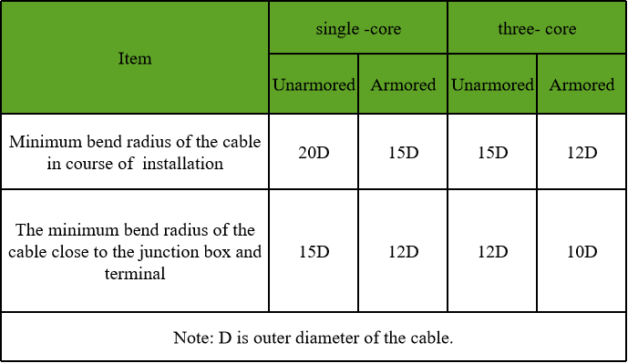
Room for the minimum bend
A shallow pit and a compact foundation leave less space than the drawing suggests, and large single core cables suffer first.
Access for testing after backfill
Whether the unit is tested with the cable connected changes which parts have to remain reachable once the pits are closed.
A ring main unit is a compact switchgear assembly that lets a distribution ring be opened and closed at a point along the route, usually with an earthing switch beside each cable connection.
How Network Configuration Reaches a Ring Main Unit
A ring closes the load path through the unit. When one section is isolated, the unit carries the load from the healthy side, so a cable can be asked to carry more than its share of the normal demand for as long as the repair lasts.
That transfer duty is a design figure, and it belongs in the enquiry. A cable selected only against its steady load may be perfectly adequate in normal operation and inadequate during the exact event the ring exists to survive.
Where a tee-off transformer is supplied from the same unit, the load paths multiply: the transformer's demand adds to the ring current, and the switching plan for an outage becomes more complicated than a simple open point.
Each of those possibilities adds an item to the cable order, and the count is settled by the network configuration rather than by the length of the route.
Cable termination dimensions belong to the unit as much as to the cable, and mismatch between the two is discovered on the day the compartment is opened.
Interface Details That Have to Match
These four points appear on both the switchgear drawing and the cable order, often in different words.
| Interface | What the unit defines | What the cable order confirms |
|---|---|---|
| Cable box and gland plate | Number, size and direction of cable entries | Cable diameter, gland type and sealing method |
| Termination cavity | Depth, bushing type and clearances | Termination type, length and fitting angle |
| Earthing switch | Duty and discharge path | Screen cross section and bonding arrangement at the unit |
| Test point | Position and access | Whether the cable end can stay connected during testing |
Exchanging these two sets of drawings early is cheaper than discovering the difference on site.
An earthing switch is closed onto a cable that has just been isolated, so its duty is set by the fault level and by the stored energy in the cable capacitance.
Where Ring Main Unit Cabling Goes Wrong
The recurring problems are commercial and documentary before they are technical.
- Cable ordered before the switchgear model was confirmed, so the terminations do not match the cavities.
- Earthing switch duty taken from a generic design note instead of the fault level at that point.
- Screen bonding decided on site after the cable compartment had already been built.
- Two cables of different constructions entering one unit, which complicates the fault duty and the spares.
- Pits backfilled before anybody proved that the test connections could still be reached.
None of these is a manufacturing fault, and each of them is settled by one meeting held early enough.
Fault level at the unit decides the screen cross section, the bonding arrangement and the test that proves the installation afterwards.
Cable Arrangements Seen at a Unit
Three arrangements cover most distribution practice, with different consequences for the order.
| Arrangement | Where it is used | What to watch |
|---|---|---|
| Three core cable | Compact distribution where space is tight | Termination depth and minimum bend radius |
| Single core cables | Higher currents and longer feeders | Spacing, screen bonding and sheath voltage |
| Two circuits in one unit | Ring with a tee-off load | Transfer duty and fault level at the unit |
The arrangement decides the number of terminations, and it also decides how the screens are treated when both circuits are in service.
Network configuration determines how many cables arrive, and therefore how many terminations, glands and earthing provisions the order contains.
A Unit That Fitted and Terminations That Did Not
Situation: A distribution project ordered switchgear kiosks first from one supplier and cable later from another, using the route drawings as the common reference.
Finding: The kiosks arrived with shallow cable compartments and angled bushings. The cable was correct, the unit was correct, and the termination selected from the cable order would not fit the cavity without a change.
Decision: Right angle terminations were substituted and the fitting sequence was rewritten, with the switchgear supplier's interface drawing attached to the cable order as a controlled document.
Result: The programme held, the change cost a week of procurement attention rather than a site delay, and every later order on the project carried the interface drawing with it.
What to Confirm Before Delivery
Four checks close the loop between the two orders.
The termination matches the cavity
Compare the switchgear interface drawing against the accessory selected for the cable, not against the previous project.
The earthing arrangement is agreed
Bonding at the unit, electrode positions and the path to the earthing switch are confirmed with the network operator rather than inferred.
The test plan is possible
The sequence of tests at commissioning should be walkable on the drawing before anything is delivered.
The labels and identification are consistent
Unit references, circuit names and cable tags should match across the drawings that site will actually use.
Earthing and Fault Level at the Ring Main Unit
The earthing switch at a ring main unit exists to make a cable safe to work on. It connects the conductors to earth before a compartment is opened, and it does that while the cable may still be holding charge.
Charge left in a long cable is not trivial, and the switch has to close onto it repeatedly without damage. That is a duty, and the duty follows from the network fault level and from the capacitance of the cable being operated.
The same fault level sizes the screen. A screen that is adequate for a modest fault current becomes the limiting item when a network is reinforced and the figure rises, which is why the assumed value belongs in the record.
A network upgrade that changes the fault level is therefore a trigger to recheck the cable screen, the bonding and the earthing provisions at every unit on the affected section.
Records at Handover
A short list of items prevents a future fault from becoming an excavation.
- Unit reference, circuit name and cable identification as they appear on site.
- Termination type fitted, with the torque applied to the connections.
- The earthing and bonding arrangement as built, not as designed.
- Test results together with the conditions they were taken under.
- The fault level values the arrangement was designed against.
Kept together, these five items answer most of the questions that arise years later.
What the Supplier Needs to See
A cable order that names the switchgear model, the cavity dimensions and the fault level usually removes all of the ambiguity. Where those are not yet fixed, a provisional sheet is better than silence.
The supplier cannot decide the network arrangement or the earthing policy, and does not need to. What the supplier can do is confirm that the construction ordered suits the duty and the space being offered to it.
Where the switchgear is chosen after the cable has been ordered, a short interface check before manufacture usually costs nothing and settles whether the terminations, the spares and the test plan will work.
RFQ Inputs for Unit Interfaces
These details let the cable, the terminations and the switchgear be checked against each other before either is manufactured.
- the switchgear model, cable compartment dimensions and bushing type
- the fault level the cable screen and earthing switch have to withstand
- the network arrangement, including transfer duty if a ring is used
- the number of circuits and cables entering each unit
- the termination type expected, with the space available to fit it
- the earthing and bonding arrangement at the unit and along the route
- the test sequence planned at commissioning
- the labelling and record format the owner expects at handover
Technical references such as IEC 60502, IEC 60228 and IEC 60332 can align cable construction and test terminology. The approved project specification, applicable local rules and qualified design authority still govern the final system decision.
JINCHUAN Cable Support for ring main units and their cable interfaces
JINCHUAN Cable supplies distribution cable whose screen and sheath can be matched to the fault level and the earthing arrangement at a ring main unit.
Review the cable range and the manufacturing profile, then send the switchgear interface drawing so the termination and the cavity agree.
Exchange the interface drawing before either product is built, because a cavity and a termination will not negotiate on site.
FAQ
What is a ring main unit?
It is a compact switchgear assembly installed at points along a distribution ring so that sections can be switched, isolated and earthed without going back to the primary substation.
Why does a unit usually have two cable connections?
Because it sits in the ring. The cables arrive from either side so that a faulted section can be isolated while the rest of the ring stays in service.
What kind of cable is used with it?
Either three core cable where space is tight, or single core cables where currents and lengths are greater. The choice changes the termination and the bonding detail.
How is the screen treated at the unit?
It is bonded in the arrangement agreed for the network, which is why the bonding detail belongs on the switchgear interface drawing as well as on the cable drawings.
What is the earthing switch for?
It connects the cable to earth before a compartment is opened, and it has to absorb the discharge from cable capacitance as well as carry fault current.
Does fault level affect the cable?
Yes. It sizes the screen and it sets the duty on the earthing provisions at the unit, so a network change can make an existing cable arrangement the limiting item.
Can terminations be reused?
Sometimes, if they are undamaged and match the cavity, but a reused termination on a new unit is a common source of hidden problems and should be a deliberate decision.
What should be recorded at handover?
Unit and circuit identification, termination type and torque, the earthing arrangement as built, test results, and the fault level the design assumed.
Does the unit change the cable size?
It can, because transfer duty during an outage may require the cable to carry more than its normal share, and that figure comes from the network configuration.
How can JINCHUAN Cable support a unit interface?
JINCHUAN Cable can confirm the screen and sheath construction of the cable ordered against the fault level and earthing arrangement at the unit.