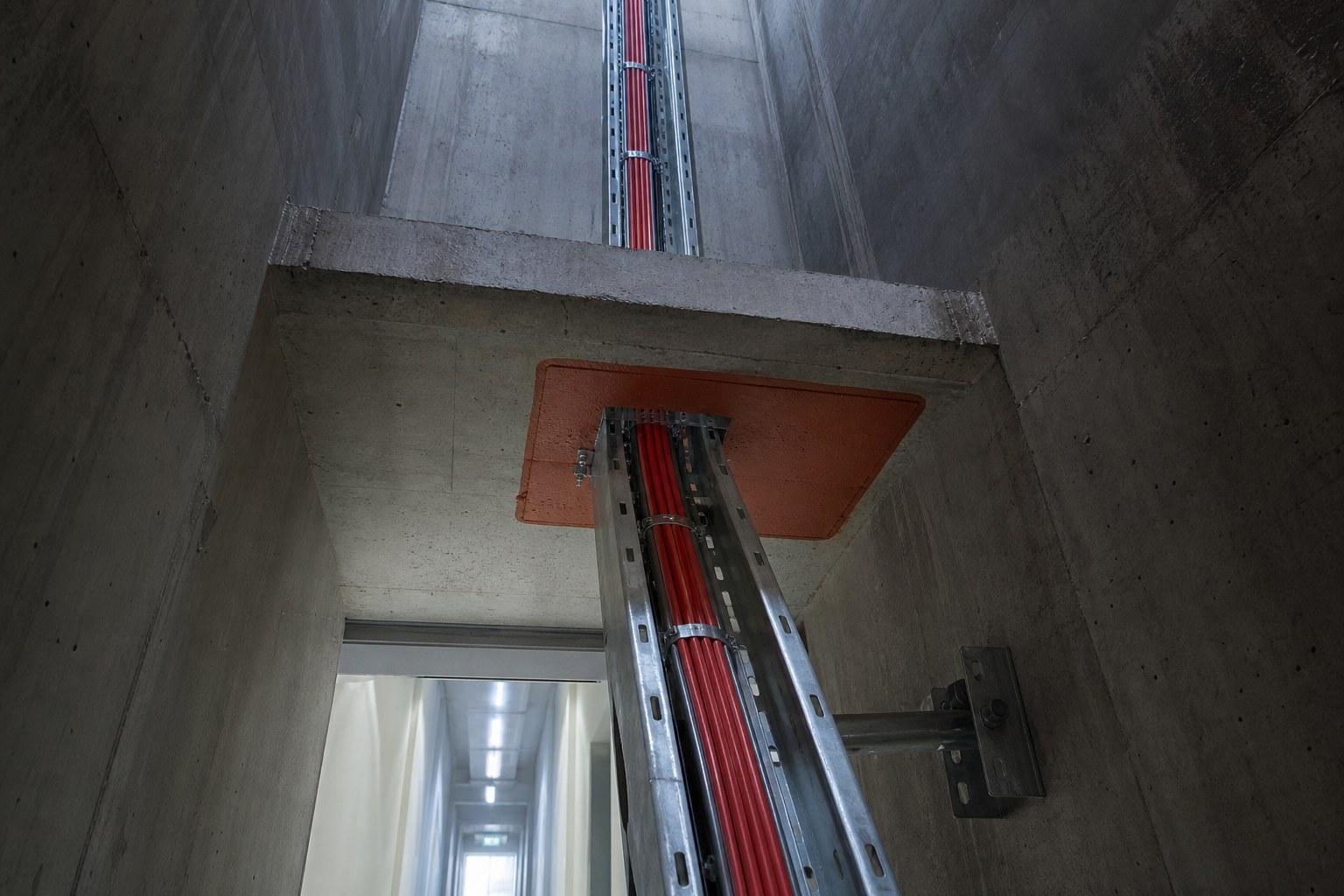

Cable Manhole Design for Safe, Maintainable Buried Routes
A cable manhole should be sized around the cable bend, jointing footprint, worker access, drainage and the surface load above it. The route designer should settle those five inputs before excavation, then verify duct entries, supports, cover class and the as-built record at handover.
Source note: OSHA 29 CFR 1910.146. For a U.S. confined-space screening reference, OSHA 29 CFR 1910.146 uses 3 defining conditions and identifies oxygen below 19.5% or above 23.5% by volume as hazardous-atmosphere thresholds. A cable manhole still has to be assessed under the rules that apply at the project location; these figures are a screening reference, not a universal chamber design specification.
"not designed for continuous employee occupancy"
Attributed to OSHA 29 CFR 1910.146.
A buried route spends almost its whole life as a line on a drawing. The parts of it that become physical are the chambers: the pits where cable is pulled, the boxes where it is jointed, and the small structures that let someone reach a duct without opening a road.
Work like this is habitually designed last and cut first when a budget tightens. The cost of that decision surfaces years later, at the moment a joint fails or a new service has to cross the same ground.
There is nothing exotic about getting it right. It means deciding early what each structure is for, sizing it around the cable operations that will happen inside it, and leaving a record that outlives the crew that built it.
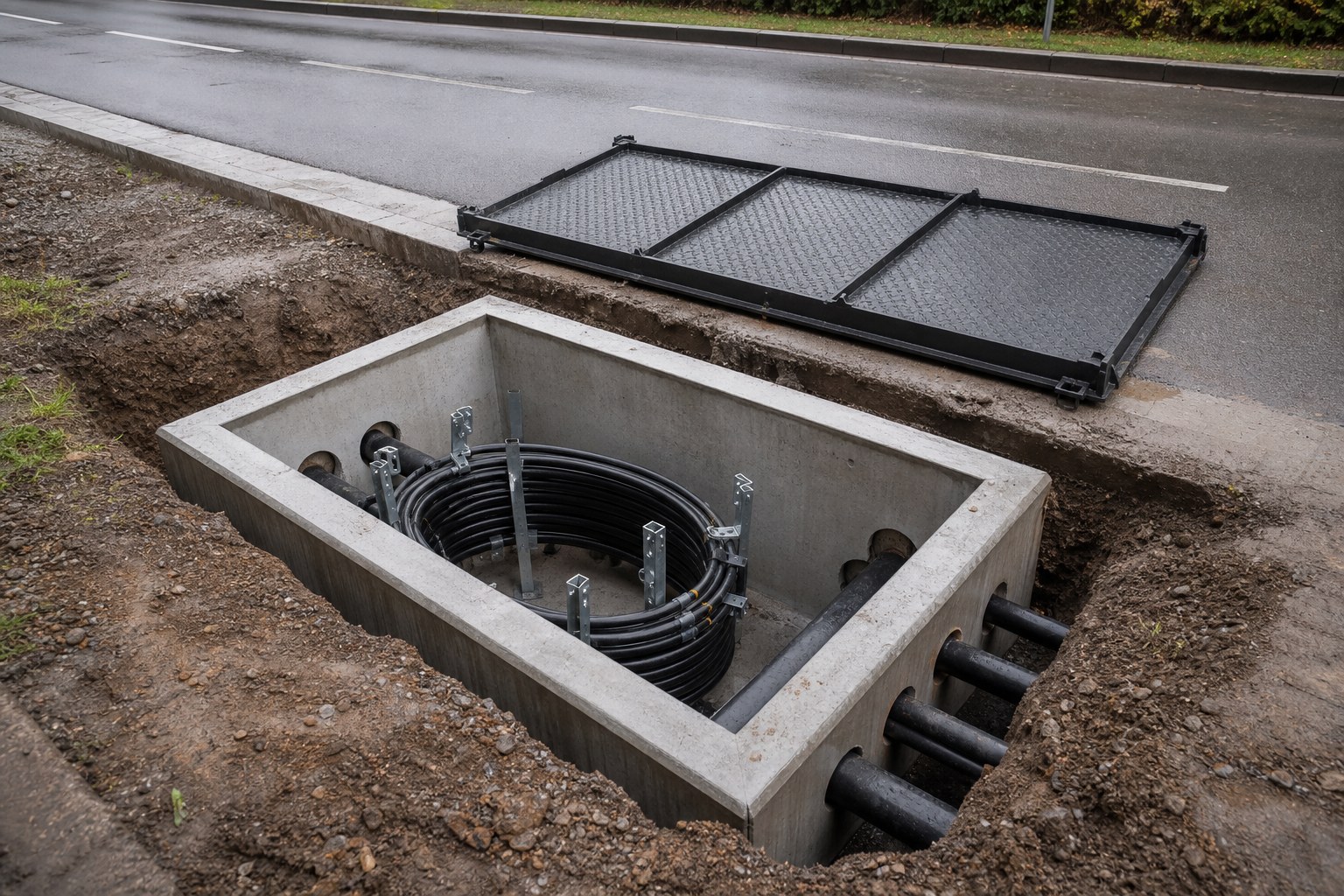
What Each Underground Access Structure Is For
A chamber big enough to work in with a person inside is normally where joints are made and where long pulls are broken into manageable lengths. It is also the point at which a buried route can be inspected without excavation.
Smaller boxes exist for simpler purposes. They provide hand access for pulling or for feeding cable, and they are sized by the duct and the operation rather than by the need to stand inside.
Bends and intermediate points often get their own structure simply because pulling around a corner needs a place to accumulate cable and to change direction under control.
Naming varies between utilities and countries, and so do dimensions. The practical approach is to agree what each structure has to support on this particular route and name it afterwards.
A cable manhole carries the heaviest duties on a route: jointing, long pulls and inspection, usually with a person working inside it.
Comparing the Three Common Structures
The categories overlap in practice, and the differences that matter are about the work expected inside them.
| Structure | Main purpose | What drives its size |
|---|---|---|
| Cable manhole | Jointing, pulling and inspection with a person inside | Bend radius, joint length, working clearance |
| Handhole | Pulling and inspection access where no work is planned inside | Duct diameter and space to feed cable by hand |
| Draw pit | Pulling at a bend or direction change | Number of services sharing it and roller access |
Final dimensions belong to the approved specification, which differs by network owner and jurisdiction.
The line between a handhole and a draw pit is practical rather than formal, and it shows up in how much room the cable needs around it.
What a Workable Cable Manhole Provides
Five requirements decide whether a structure is usable five years after handover.
Room to bend the cable
The internal space has to allow the cable to follow its minimum bend radius while people and equipment are also inside.
A floor that drains
A fall to a sump, or a connection to a drainage system, keeps water away from joints and from anyone working in the pit.
Walls that do not damage the sheath
Smooth or lined internal surfaces matter wherever cable is pulled across a corner under tension.
Cable supports that stay put
Brackets, bearers or racks keep cable clear of the floor and hold it while jointing work is in progress.
A cover that suits the location
Pedestrian, carriageway and heavy-duty situations call for different loading classes, frames and bedding arrangements.
Loading class, cover type and frame bedding decide whether the structure survives traffic, and all three are cheap to settle before excavation.
Sizing a Cable Manhole Around the Pull
A chamber is usually drawn as a rectangle with a dimension on each side. Those dimensions come from the cable, and only two things matter at the start: how tightly the cable can bend, and how much of it has to be laid out before a pull begins.
Where a cable enters through a duct and leaves through another, the geometry inside the chamber determines the side load on the sheath. Space that looks generous on a drawing can still produce a hard change of direction once the duct positions are marked on site.
Joints add their own length. A straight joint, a tee or a transition between two cable types each needs a defined footprint, plus clearance for the tools and the people using them, plus somewhere for the cable ends to rest while the work proceeds.
The sensible order is to fix the cable first, then the jointing method, and only then draw the chamber around them. Reversing that order is how a route acquires a chamber that is technically compliant and practically awkward.
Chamber drainage is the most common source of avoidable maintenance, because standing water shortens the life of nearly everything inside it.
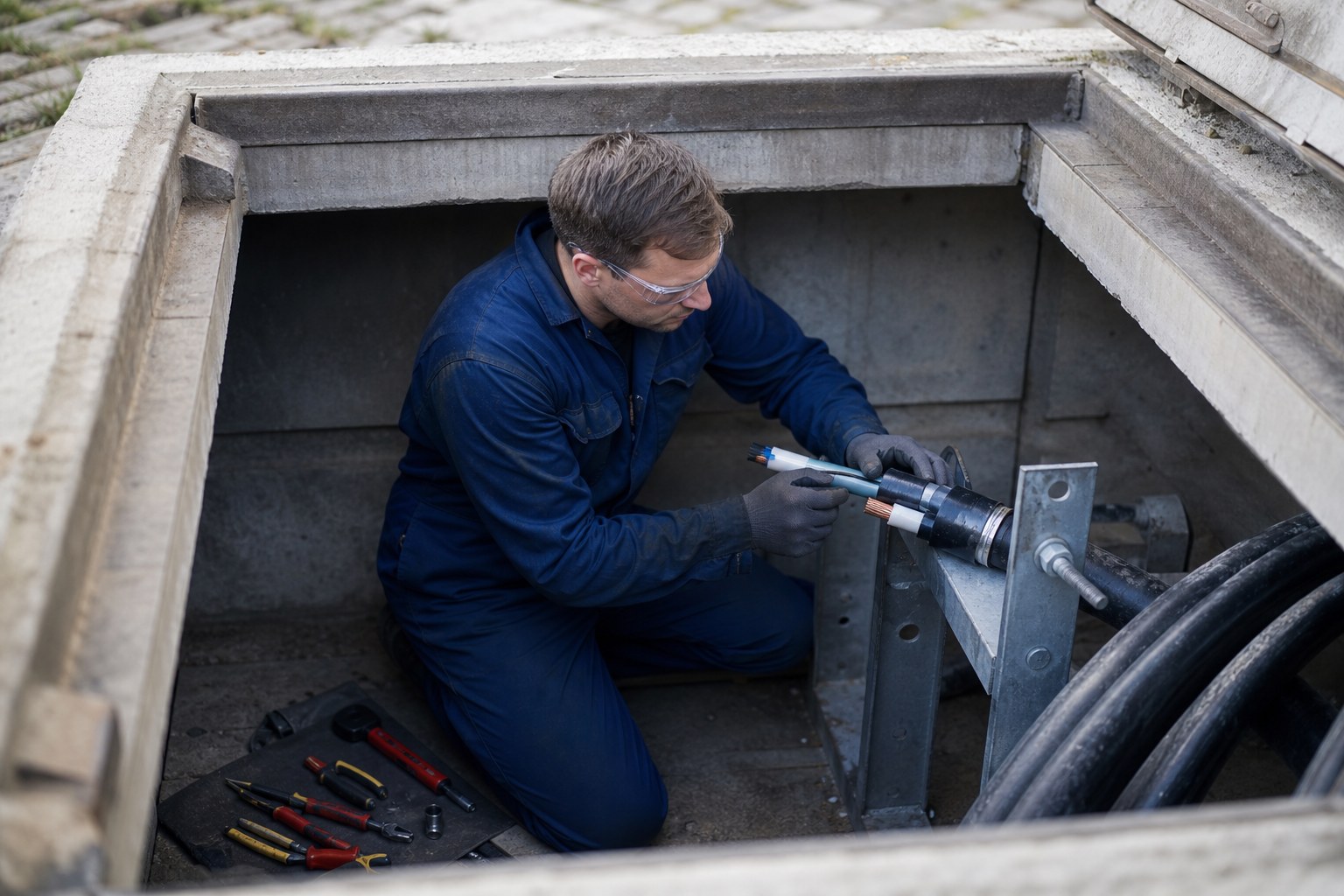
Loading and Cover Considerations
Where the structure sits decides what it has to carry, and that decision belongs to the civil design rather than to the cable supplier.
| Location | Typical loading situation | What it drives |
|---|---|---|
| Footpath or verge | Occasional pedestrian or light maintenance traffic | Moderate cover class with a stable frame |
| Carriageway or yard | Regular vehicle loading including heavy axle weights | Heavier cover class, concrete surround, deeper frame bedding |
| Inside a plant | Forklift and mobile plant movements | Cover class agreed with the site, plus protection from impact |
A cover chosen from habit rather than from the traffic above it is a recurring and entirely avoidable failure.
A cable manhole that is documented properly can be found, opened and worked in by someone who has never walked the route before.
A Joint Bay That Filled With Silt
Situation: A distribution route crossed a landscaped area that drained towards the new chamber. The chamber was built to the right dimensions and finished neatly, and the surface above it was reinstated to match the surrounding paving.
Finding: Within two seasons the pit held a layer of silt deep enough to bury the cable supports. Surface water had been finding its way in through the cover seating, and the small fall intended inside the chamber had been lost during construction.
Decision: The chamber was cleaned out, the floor re-formed with a proper fall, and the cover frame was re-bedded and sealed. Photographs of the finished floor were added to the route record so the fall could be checked at the next inspection.
Result: The chamber has stayed dry since. The change cost one day of work at construction stage and would have cost a cable joint if it had gone unnoticed for another year.
Drainage and Water Management Choices
Water is the enemy of every buried chamber, and the options are straightforward even if the site is not.
- A fall to a sump, with a pump or a soakaway depending on the water table.
- A sealed floor where drainage is impossible, accepting that water will be removed manually.
- Correctly bedded covers and frames that keep surface run-off out rather than channelling it in.
- Duct entries sealed around the cable after installation, so the route itself does not become a drain.
- A check at handover that the fall still exists after the frame and cover have been installed.
Most of these cost very little at construction stage and become expensive once the surface above has been reinstated.
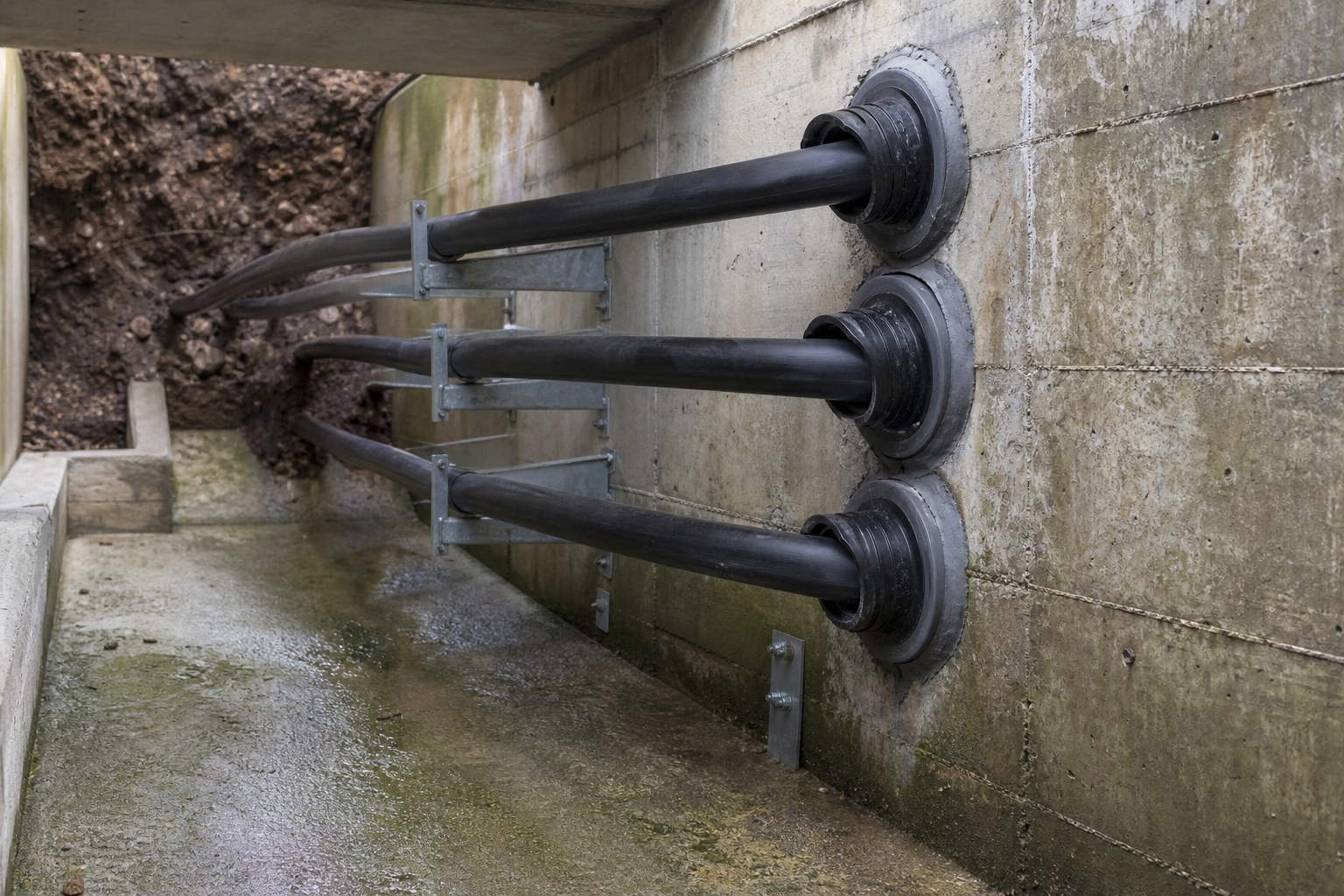
Records Worth Keeping for Cable Manholes
Four items turn a hidden structure into something the next team can work with.
Position and depth
Coordinates or a measured offset from a permanent feature, plus the depth of cover over the ducts entering the chamber.
Construction and lining
Material, internal dimensions and the installed depth, recorded before backfill rather than reconstructed from memory.
What is inside
Cable identities, joint types, support positions and any spare ducts or draw ropes left for future use.
Photographs before backfill
Images of the ducts entering, the floor fall and the finished chamber are the cheapest record a project can keep.
Access, Confined Space and the Cable Manhole Visit
A chamber is entered by people, and that single fact brings a set of obligations that have nothing to do with cable. Access arrangements, atmosphere testing and rescue provision belong to the site's safe system of work.
What the cable design can do is make those visits shorter and less frequent. Cable that is supported clear of standing water, labelled at the entry point and routed so it does not obstruct the ladder is cable that gets inspected on schedule.
Access points also need to suit the equipment that will arrive. A pit that cannot take a jointing van close by, or that has no space to lay out a drum, turns a routine activity into a project of its own.
Questions Before the Excavation Starts
Five answers settle most of the design before anyone breaks ground.
- What work will happen inside this structure, and how much clearance does that work need?
- What cable sizes, joint types and bend limits will pass through it over the life of the route?
- What loading will the surface above it carry, and which cover class follows from that?
- Where will water go, and what happens in the wettest month of the year?
- What record will be handed over, and who is responsible for producing it?
A route with clear answers to these questions is one that can be maintained without guesswork.
RFQ Details for Chambers and Draw Pits
These details let the chamber, the ducts and the cable be reviewed as one buried installation.
- the route drawing with chamber positions marked
- cable types, sizes and minimum bend radius at each structure
- jointing method and the footprint each joint needs
- duct sizes, quantities and entry positions in each wall
- loading situation above the structure and the cover class required
- drainage arrangement and the expected water table
- support or racking arrangement inside the chamber
- the record format the owner expects at handover
Technical references such as IEC 60502, IEC 60228 and IEC 60332 can align cable construction and test terminology. The approved project specification, applicable local rules and qualified design authority still govern the final system decision.
JINCHUAN Cable Support for buried cable routes and jointing chambers
JINCHUAN Cable supplies conductors and insulated cable whose bending, mass and diameter figures feed directly into chamber sizing, and can confirm what each construction needs from the route.
Review the cable range and the manufacturing profile, then share the route drawing so the buried structures can be planned around the cable being delivered.
Read About JINCHUAN Cable or Contact JINCHUAN Cable with the project voltage, route and service conditions.
Settle the cable, the joint and the chamber together, before the excavation is priced, because the cheapest moment to change a buried structure is the one before it exists.
FAQ
What is the difference between a cable manhole and a handhole?
A manhole is large enough for someone to enter and work in, while a handhole provides access for pulling or inspection without entry.
Why are draw pits needed at bends?
They give the cable somewhere to be accumulated and redirected, which keeps side loads on the sheath within the limits set for the pull.
How deep should a chamber be?
Depth follows the duct levels, the required cover over the ducts and the working height needed inside, so it is a design output rather than a standard figure.
Is drainage always required?
Not always, but water has to go somewhere. Where drainage is impossible, the design should assume manual removal and keep cable clear of the floor.
Which cover class should be used?
The one that matches the traffic above it. Footpath, carriageway and plant yard situations call for different loading classes and bedding arrangements.
Should ducts be sealed around the cable?
Yes. Sealing stops the duct acting as a drain into the chamber and keeps silt and groundwater out of the route.
What causes cable sheath damage inside chambers?
Sharp corners, unprotected wall entries and cable pulled hard against a support are the usual causes, and all are avoidable at construction stage.
How often should a cable manhole be inspected?
The interval is set by the network owner, and it is usually driven by how accessible the structure is and what condition it was left in.
Can spare ducts be included?
Many owners include them for future services, and the record should state clearly what was left, where it terminates and how it is identified.
How can JINCHUAN Cable help with chamber planning?
JINCHUAN Cable provides cable mass, diameter and bend limits, which determine the internal space and the supports a chamber needs.