
Ask two contractors how far apart cable cleats should be and the answers will differ, and both may be quoting a rule carried over from another project.
Cable support spacing is not a house style. It follows from the mass of the cable, the forces a fault puts between conductors, the movement the route allows and the arrangement the cleat system was tested in.
Put those four inputs on the table and the spacing stops being an opinion.
What a Support Is Actually Doing
A support does three jobs at once. It carries the cable weight, it holds the cable against the forces that appear during a fault, and it keeps the cable inside its bend radius as the route turns.
Spread the supports too far apart and the cable sags between them, the sheath takes a load it was not designed for, and a fault can throw the conductors further than the arrangement can resist.
Place them too close and the cost of steel and labour climbs for no gain, and on a long route that can become the largest single item in the installation.
The interval that satisfies all three jobs is the one the cleat system was qualified at, not a figure chosen at the desk.
Cable support spacing is settled by the mass of the cable, the fault forces, the movement the route allows and the tested arrangement of the cleat.
The Four Loads a Support Carries
Four loads decide the interval, and they rarely peak together.
Weight
The mass per metre of the cable multiplied by the length between supports sets the static load, and on a vertical run that number grows quickly with depth.
Fault forces
During a short circuit the conductors repel or attract each other with a force that depends on the peak current and the spacing between phases.
Thermal movement
A cable changes length as load changes, and whether the route lets it move or restrains it changes what the supports have to resist.
Bend radius
At every change of direction the cable has to stay inside its minimum radius, and the supports on either side of the bend decide whether it does.
Cleat spacing on a vertical run is shorter than on a horizontal run, because each support carries the whole weight of the cable below it.
Where the Inputs Come From
Four documents supply everything the calculation needs.
| Input | Comes from | Why it matters |
|---|---|---|
| Cable mass per metre | Datasheet for the construction | Sets the static load |
| Peak fault current | System study | Sets the magnetic force |
| Route geometry | Layout drawing | Sets the worst case position |
| Cleat system data | Tested arrangement from the maker | Sets the qualified interval |
Four documents, and cable support spacing follows from them rather than from a habit.
Cable tray support spacing and cleat spacing are two different decisions, and confusing them is a frequent source of a rejected installation.
Why Site Conditions Beat the Drawing
The layout shows the route. It rarely shows what the route passes through.
- A tray that changes level introduces a vertical load that a horizontal interval does not cover.
- A support fixed to light gauge steel behaves nothing like one fixed to a concrete wall.
- A route through a hot area changes the temperature the cable reaches, and that changes how far it moves.
- A support under a walkway has to survive knocks that a support against a ceiling never sees.
Each one changes cable support spacing on that section.
Riser cable clamping has to hold the weight without crushing the sheath, so the clamp profile matters as much as the interval.
Case: A Riser That Pulled Its Cleats
Situation: A plant ran three single core cables up the outside of a building to reach a roof mounted transformer, using the same cleat interval that had worked on the horizontal tray below.
Finding: The vertical section carried the full weight of the run, and the lower cleats deformed over the first months. Two clamps had also been supplied in a magnetic material, and the sheath showed local heating beside them.
Decision: The riser was re-supported at a closer interval taken from the tested arrangement, the clamps were replaced with non-magnetic ones, and the fault duty was checked against the cleat data.
Result: The riser has held position since, and the horizontal figure is no longer copied onto vertical work on that site.
Short circuit forces cable conductors apart with enormous force, and the cleat system has to be selected for the peak current of the installation.
Thermal Movement Has to Go Somewhere
Every cable changes length as it heats and cools. The question is not whether that movement happens, but where it is allowed to happen.
A route that restrains the cable along its whole length pushes the movement to the ends, where it arrives at the termination. A route that allows movement in the middle lets the cable breathe between fixed points.
Either approach can work, and both have to be designed. What fails is a route where nobody decided, so the movement finds a weak cleat or a termination that cannot take the load.
Arrangements and What They Fix
Four arrangements cover most installations.
| Arrangement | What it does | Watch for |
|---|---|---|
| Fixed throughout | Restrains movement completely | Load pushed to terminations |
| Fixed at intervals with free spans | Lets the cable move between points | Abrasion where it slides |
| Closer interval on vertical runs | Carries the weight of the drop | Clamp pressure on the sheath |
| Non-magnetic clamps on single core | Avoids induced heating | Mixed materials at one support |
Each row is a decision, and each one changes cable support spacing.
Before the Cleats Are Fixed
Four checks catch most failures before they are built in.
Confirm the tested arrangement covers this case
An interval qualified for a trefoil formation does not transfer to a flat formation or to a different fault level.
Check the material
Single core circuits need non-magnetic clamps, and mixing materials at one support invites corrosion.
Look at the substrate
A support is only as strong as what it is fixed to, and a light gauge panel rarely matches a tested arrangement.
Mark the positions first
Positions transferred to the structure before drilling avoid a support that lands in the middle of a bend.
Common Mistakes in Spacing
The same errors keep appearing on site.
- Copying a cable support spacing figure from another project without checking the mass or the fault level.
- Treating the tray support interval and the cleat interval as the same number.
- Measuring from the centre of a bend instead of from the tangent point.
- Ignoring the extra load where a cable leaves a tray and turns into a vertical drop.
- Leaving the fault current out of the enquiry, so the cleat cannot be selected at all.
Every one of them is cheap to avoid on paper and expensive to correct on a riser.
Getting the Enquiry Right
Most cleat problems start in the enquiry, where the fault level and the cable mass are missing and the supplier has to assume a default.
Send the construction, the route geometry and the fault duty, and the arrangement can be selected against all three. Leave one out and the answer stops being specific.
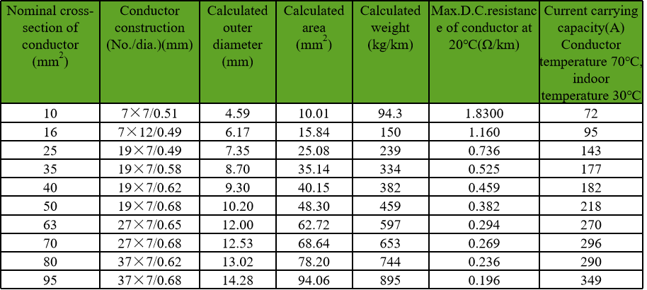
The cable supplier can provide the mass, the diameter and the construction data the load calculation needs, and can confirm how the sheath will behave under a clamp.
RFQ Inputs for Support Design
These details let the support arrangement be selected rather than assumed.
- the cable construction, with mass per metre and overall diameter
- the number of cores, and whether single core cables run in trefoil or flat
- the peak short circuit current and its duration
- the route geometry, including horizontal runs, risers and bends
- the substrate each support will be fixed to
- the maximum and minimum ambient temperature along the route
- whether the cleat system has to be non-magnetic
- the expected movement at the terminations and the arrangement there
Technical references such as IEC 60502, IEC 60228 and IEC 60332 can align cable construction and test terminology. The approved project specification, applicable local rules and qualified design authority still govern the final system decision.
JINCHUAN Cable Support for support arrangement design for tray, riser and buried routes
JINCHUAN Cable supplies the construction, mass and diameter figures that a cable support spacing calculation needs, and can confirm how the sheath behaves under a clamp.
Review the cable range and the manufacturing profile, then send the route and the fault duty so the arrangement can be checked against both.
Send the fault duty with the construction, and the support interval becomes a calculation instead of a habit.
FAQ
How far apart should cable cleats be?
The interval comes from the tested arrangement of the cleat system together with the cable mass, the route geometry and the fault level, so there is no single cable support spacing figure.
Why is spacing closer on vertical runs?
A vertical run transfers the weight of the cable below each support into that support, so the load grows with depth.
What does short circuit current have to do with cleats?
During a fault the conductors experience large magnetic forces, and the supports have to hold the cable against them.
Do single core cables need special clamps?
Yes. Magnetic materials near single core cables can heat up, so non-magnetic clamps are normally used.
Is the tray interval the same as the cleat interval?
No. The tray interval supports the tray, while the cleat interval holds the cable against its own loads.
Where does thermal movement go?
Either to the terminations on a fully restrained route, or between fixed points on a route that allows movement, and the choice has to be made deliberately.
What happens when supports are too far apart?
The cable sags, the sheath takes loads it was not designed for, and a fault can move the conductors further than the arrangement can resist.
What data should go with the enquiry?
The construction with mass and diameter, the route geometry, the fault level and the substrate the supports will be fixed to.
Does bend radius affect support positions?
It does. The supports on either side of a bend decide whether the cable stays inside its minimum radius as it turns.
How can JINCHUAN Cable help with support design?
JINCHUAN Cable can supply the construction, mass and diameter figures and confirm how the sheath behaves under a clamp.