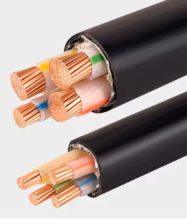

A cable can stay within its stated minimum bend radius and still be damaged during a difficult pull. Power cable pulling sidewall pressure concentrates load where the cable changes direction, enters a duct or bears against a roller. The risk becomes visible only when route geometry and pulling method are reviewed together.
A cable bend pressure calculation, cable pulling roller spacing plan and cable duct entry protection are practical controls, not optional drawings. They help the crew decide where to slow, reposition, stop or inspect before a hidden deformation reaches an inaccessible section.
This guide follows a pull from route walkdown to post-installation inspection, with attention to the small interfaces that decide whether a long route remains serviceable.
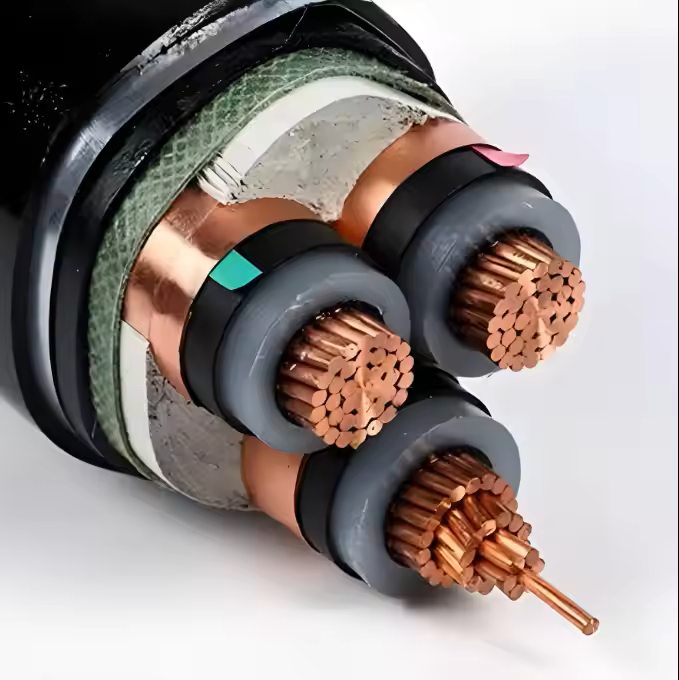
Why Straight-Line Tension Does Not Tell the Whole Story
The highest local load may occur where the route turns, not where the pulling machine reads its peak.
- A bend redirects pulling force and creates a reaction at the cable sidewall.
- Small-radius turns multiply pressure where the cable contacts a roller or guide.
- Entry transitions can pinch a cable before it reaches the planned duct or tray path.
- Roller tilt, missing supports or debris can create a local point load.
- A heavy cable can settle between rollers and increase contact force during a slow pull.
- Changing direction or pulling from the opposite end can change the critical bend.
The route plan should identify local pressure points before the cable is committed to the pull.
Power cable pulling sidewall pressure should be reviewed with bend radius, cable weight, pulling tension, friction, roller geometry and route direction.
The Pulling Tension Was Acceptable Until the Cable Reached the Duct Entry
Situation: A contractor pulls a large feeder through a long trench and records tension below the approved limit. Near the final entry, the cable sheath shows a flattened mark.
Finding: The entry bell was too short and one roller had shifted away from the tangent line. The cable met the bend-radius rule in the drawing but contacted a sharp transition under load.
Decision: The crew stops, preserves the position, inspects the entry and adjacent length, corrects the guide geometry and repeats the pull only after the route release is reapproved.
Result: A local pressure problem is corrected before the cable enters a sealed duct, and the final record explains why the first pull was rejected.
A power cable pulling sidewall pressure review can reveal risk even when the calculated straight-line tension remains below its limit.
Route Features That Change Local Pressure
Mark these features on the pull plan and inspect them during the work.
| Feature | Pressure concern | Control to verify |
|---|---|---|
| Horizontal bend | Cable bears against outer radius | Roller size, spacing and tangent |
| Vertical transition | Weight adds to contact force | Support, guide and lifting method |
| Duct entry | Edge can pinch or scrape sheath | Bell mouth, alignment and cleaning |
| Tray step | Cable may drop onto an edge | Transition roller and side restraint |
| Multiple cables | Adjacent cables alter movement | Sequence, separation and route width |
| Pulling eye | Force may not enter cable evenly | Approved attachment and inspection |
A risk mark should remain on the as-built pull record when the feature affects future replacement or access.
Control power cable pulling sidewall pressure with suitable rollers, entry bells, spacing, communication and a defined stop rule.
Set Roller Geometry From the Cable, Not the Route Name
Cable pulling roller spacing should reflect cable diameter, weight, stiffness, bend direction and the actual support surface. A generic spacing copied from a smaller feeder can let a heavy cable sag and touch the tray or trench between supports.
At bends, the roller must support the cable along the intended curve. Tilted or undersized rollers can make the cable climb, pinch or slide sideways. The crew should be able to see and communicate the condition during the pull.
The plan should also state how rollers are restrained, how they are checked after a pause and who can add or reposition one without losing control of the workfront.
Power cable pulling sidewall pressure evidence should connect route sections, equipment settings, observations and post-pull inspection to the installed cable.
Inspect Four Moments That Often Hide Damage
A short inspection at the right moment is more useful than a long review after the route is closed.
Before the pull
Check route cleanliness, bell mouths, roller line, drum direction, pulling eye, communications and stop signals.
At the first bend
Observe cable seating, roller rotation, side movement and whether the actual curve matches the planned radius.
After a pause or obstruction
Confirm the cable has not settled onto an edge and that the machine restarts without a shock load.
At the final entry
Inspect sheath, alignment, protection and tail length before the cable disappears into the duct or equipment.
The RFQ should state power cable pulling sidewall pressure assumptions, route survey data, equipment responsibility and damage response.
Stop the Pull When These Signals Appear
The crew needs an explicit stop rule before pressure becomes permanent damage.
- A roller stops turning, tilts or moves from the planned line.
- The cable climbs a flange, contacts an edge or twists at a transition.
- Tension rises sharply without a corresponding route explanation.
- Communication fails between drum, pulling machine and bend stations.
- The cable sheath shows whitening, flattening, gouging or unexpected marks.
- A duct entry, trench section or access point differs from the released survey.
A stop is a controlled protection of the cable and schedule; restarting without inspection can multiply both risks.
Evidence After a Difficult Pull
Capture enough detail to show what the installed cable experienced.
| Evidence | What it should show | Use later |
|---|---|---|
| Route log | Sections, bends, pauses and crew observations | Investigate anomalies |
| Equipment log | Machine setting, tension and speed | Compare with method |
| Photographs | Drum, bends, entries and cable condition | Support acceptance or claim |
| Inspection | Sheath, ends, dimensions and marks | Confirm no visible damage |
| Test results | Applicable post-pull electrical or sheath checks | Release before concealment |
| Deviation | Route or method change and approval | Preserve final baseline |
A pull number without cable identity and route position is difficult to use when a future fault appears.
Protect the Cable at the Duct Boundary
The transition into a duct deserves its own release check.
Verify the bell mouth
Use a smooth, correctly sized entry that remains aligned under the expected pulling force and cable movement.
Control the bend
Support the cable through the tangent and confirm the first section inside the duct cannot drop onto an edge.
Manage lubricant and debris
Apply only compatible materials and remove standing water, grit or objects that can abrade the sheath.
Record the concealed length
Capture tail, route reference and inspection status before the entry is sealed or buried.
A Good Pull Plan Includes Recovery, Not Just Success
Long routes can meet an unexpected obstruction, weather delay or equipment failure. The plan should state how the cable will be held, protected, inspected and restarted without creating a shock load or uncontrolled bend.
Cable pulling damage prevention also includes drum handling after a pause. Keep the cable supported, prevent water entry and maintain end seals while the team decides whether to continue, reverse or reconfigure the route.
The recovery decision should be documented when it changes the route, force history or inspection scope.
The Installed Cable Is the Final Test of the Pull Method
A route can be accepted only after the cable's visible condition, end preparation, route identity and required tests are reviewed. Do not let a successful payout substitute for inspection at the places where sidewall pressure was highest.
Keep the pull log with the cable and route records. It gives future teams context if a sheath issue, joint problem or replacement difficulty appears years later.
JINCHUAN Cable can clarify construction, finished diameter, bend radius and handling information for the ordered cable, while the installation team remains responsible for the released route method.
RFQ Inputs for Pulling Sidewall Pressure Control
State power cable pulling sidewall pressure assumptions in the RFQ so bidders include route geometry, equipment, controls and post-pull evidence.
- cable construction, diameter, mass, bend radius and approved pulling limits
- route survey with bends, levels, entries, transitions, ducts and access points
- cable bend pressure calculation basis and friction or force assumptions
- roller type, cable pulling roller spacing, entry protection and support method
- drum, pulling eye, machine, lubricant, communication and stop-rule requirements
- crew qualifications, supervision, inspection and hold points
- post-pull sheath, electrical, dimensional and photographic evidence
- damage, obstruction, pause, reversal, rework and claim responsibility
Technical references such as IEC 60502, IEC 60228 and IEC 60332 can align cable construction and test terminology. The approved project specification, applicable local rules and qualified design authority still govern the final system decision.
JINCHUAN Cable Support for power cable pulling through trays, ducts and route bends
JINCHUAN Cable can provide cable construction, diameter, mass, bend-radius and handling data for a project pull plan.
Review JINCHUAN Cable products and the company profile, then send the route survey and pulling limits for a project-specific response.
Release the route, rollers and duct entries, then document power cable pulling sidewall pressure controls before the first drum moves.
FAQ
What is power cable pulling sidewall pressure?
It is the local reaction and contact load created where a cable changes direction or bears against a roller, guide, tray or duct entry during pulling.
Can a cable meet bend radius and still be damaged?
Yes. Local pressure, edge contact, roller geometry, shock loading or a poor transition can damage the cable even when the nominal radius is respected.
What is a cable bend pressure calculation?
It is a route-specific assessment of bend geometry, pulling force, cable weight, friction and contact conditions used to identify local risk.
Why does cable pulling roller spacing matter?
Spacing controls sag, contact and support between rollers; it should match cable diameter, mass, stiffness and route conditions.
What is cable duct entry protection?
It includes smooth aligned bell mouths, support through the tangent, debris control and inspection before the cable disappears into the duct.
When should the crew stop a pull?
Stop when rollers shift, communication fails, tension changes sharply, the cable contacts an edge, damage appears or the released route differs from reality.
What should a post-pull record include?
Include cable and route identity, force or equipment logs, observations, photographs, inspections, tests and approved deviations.
How should a pull pause be managed?
Support and protect the cable, maintain end seals, inspect the condition and approve a controlled restart or revised method.
Who owns pulling damage?
The contract should allocate responsibility by route readiness, equipment, method, handling, inspection and custody evidence.
How can JINCHUAN Cable support a pull plan?
JINCHUAN Cable can provide ordered cable dimensions, mass, bend-radius and handling data for qualified installation planning.