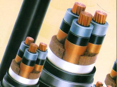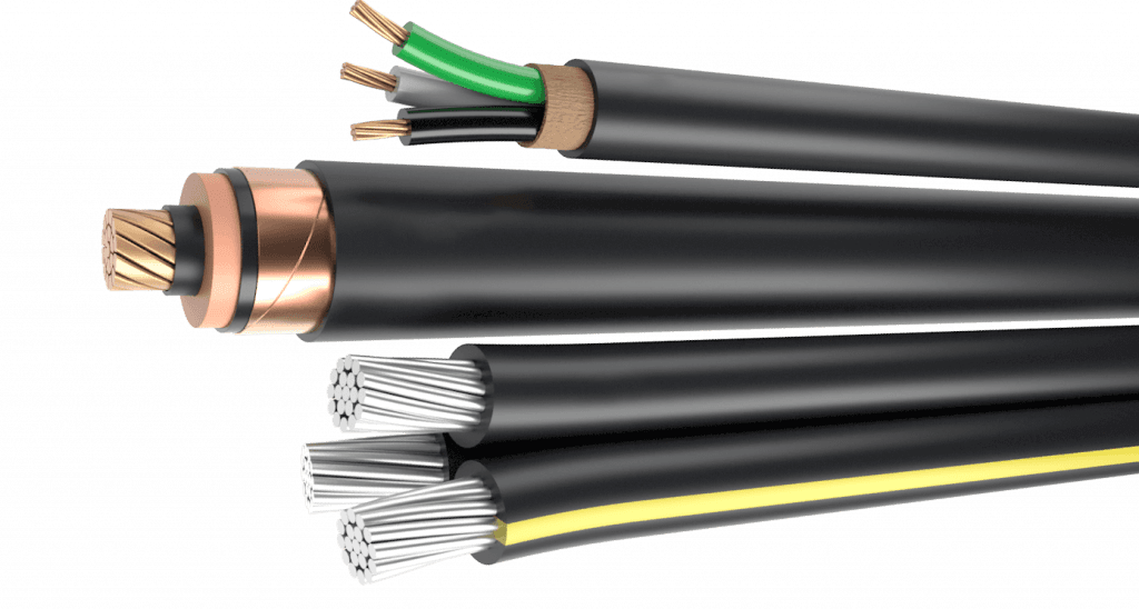

On a long single core feeder, the metallic screen is not only a shield. It is a conductor running the full length of the route in parallel with the current carrying core.
Left alone, that screen picks up an induced voltage from the core, and how the screens are bonded at each end decides what happens to it. Cross bonding is one of the three answers, and it is the one long routes usually reach for.
The choice is a system decision rather than a cable decision, and it still reaches back into the cable, the joints and the accessories that get ordered.
Three Ways to Bond a Screen
Three arrangements cover most installations, and each one trades something different.
| Arrangement | What happens to the screen voltage | Where it suits |
|---|---|---|
| Both ends bonded | Circulating current in the screen | Short runs and low currents |
| Single point bonded | Standing voltage at the free end | Short to medium runs |
| Cross bonded | Induced voltages largely cancel | Long single core feeders |
It is a system question first, and the cable construction follows from the answer.
Cross bonding transposes the screens at joint bays so the voltages induced along the route largely cancel instead of adding up.
What Screen Current Does to Losses
A screen bonded at both ends forms a closed circuit around the core. Current flows in it, and that current produces heat inside the cable while doing nothing useful.
The effect grows with load and with route length, and it shows up as a reduction in how much current the cable can carry. On a long feeder the reduction is not marginal.
That is why long routes move away from the simple arrangement. The alternative is either to remove the return path altogether or to make the induced voltages cancel each other.
Bonding both ends is the simplest arrangement and the one that produces circulating current in every screen along the feeder.
What the Transposed Arrangement Requires
Five things have to be true before this arrangement works on site.
A joint bay at every transposition
The screens are rearranged at a joint, so the route needs joints at fixed intervals and those positions have to be buildable.
Sections of near equal length
The cancellation depends on the sections matching. A route change that shortens or lengthens one of them leaves a residual voltage behind.
Link boxes at each bay
The transposition and the earthing connections are made in link boxes, which need accessible positions and a footing that will not move.
A plan for the free ends
Wherever a screen is not bonded, the standing voltage there has to be limited by a device selected for that duty.
A route that has been surveyed
Section lengths are measured rather than assumed, so the alignment has to be surveyed before the joints are ordered.
Single point bonding removes the circulating current and leaves a standing voltage at the unbonded end that has to be limited.
Where the Arrangement Goes Wrong
The failures are rarely in the theory.
- Section lengths that drift from the design because a crossing moved during construction.
- Link boxes placed where nobody can reach them for testing.
- A bond left disconnected after maintenance and never written down.
- A joint replaced with a standard one, losing the transposition at that bay.
Cross bonding works on paper easily, and on site only if the routine around it is written down.
Cable screen earthing and bonding arrangements belong in the enquiry, because they change the joints, the link boxes and the accessories ordered with the cable.
Case: A Feeder That Would Not Reach Its Rating
Situation: A plant found that a long single core feeder ran hotter than the load calculation predicted, and the screens showed a measurable circulating current.
Finding: The route had been bonded at both ends throughout, and the sections were long enough that the induced voltage drove a screen current which added to the losses and pulled the cable down from its free air rating.
Decision: The arrangement was rebuilt with transposed screens at the existing joint bays, link boxes were installed at each one, and the section lengths were surveyed and recorded.
Result: Screen current fell, the operating temperature followed it down, and the record of section lengths moved from a construction note into the maintenance file.
Link box positions and accessible ground have to be agreed early, since the arrangement cannot be completed at the end of a project.
Why the Sections Have to Match
The cancellation in a transposed arrangement depends on the three sections behaving alike. If one is materially shorter, its contribution no longer cancels the others.
What remains is a standing voltage at the ends and a residual current in the screens, which is exactly what the arrangement was meant to remove. Nothing fails immediately, and the cost comes back as losses.
Surveying the alignment before the joints are ordered is what protects the design. Moving a joint because a crossing landed awkwardly is how a balanced arrangement becomes an unbalanced one.
Who Owns Which Deliverable
Four items make the arrangement real.
| Item | Needed for | Owner |
|---|---|---|
| Section lengths | Balanced transposition | Design and survey |
| Joint bays | Making the transposition | Civil and design |
| Link boxes | Bonding and testing access | Design and operations |
| Voltage limiting devices | Unbonded screen ends | Design authority |
Each row is somebody's deliverable, and cross bonding is only as good as the weakest of them.
Questions to Settle Before Ordering
Three answers decide what travels with the cable.
Which arrangement applies?
Both ends bonded, single point bonded or transposed, decided on the system rather than on the drum.
Where are the transposition points?
They have to fall at joints, so the route survey and the joint schedule have to agree with each other.
How will the screens be tested later?
Testing access belongs in the design, because a link box nobody can reach is a link box nobody will check.
What This Changes on the Order
The arrangement reaches back into the cable and the accessories.
- Joint quantities and positions, because each transposition happens at a joint.
- The screen cross section, because it carries fault current as well as any residual current.
- The accessories list, including link boxes and any device used to limit standing voltage.
- The documentation, because section lengths and cross bonding points end up in the record.
None of that is visible on a drum, and all of it depends on a decision made before the order.
Settling It Early
Bonding arrangements are usually decided by the system designer, and they are usually decided late, once the route is fixed and the joints are already scheduled.
Bringing the question forward, even as a provisional plan, changes what can be ordered in the same shipment as the cable.
A supplier can build the cable and the screen to suit whatever the arrangement needs. What no supplier can do is reconstruct a balanced transposition from a route that was never measured.
RFQ Inputs for Bonding Arrangements
These details let the cable, the joints and the accessories be ordered as one package.
- the bonding arrangement proposed for the route
- the route length and the number of transposition points
- the planned section lengths between joints
- the screen cross section required for fault current
- the link boxes and voltage limiting devices expected
- the earthing arrangement at each end
- the route survey showing accessible positions for link boxes
- the documentation expected for the bonding record
Technical references such as IEC 60502, IEC 60228 and IEC 60332 can align cable construction and test terminology. The approved project specification, applicable local rules and qualified design authority still govern the final system decision.
JINCHUAN Cable Support for screen bonding arrangements for long single core feeders
JINCHUAN Cable supplies single core cable with screen and sheath arrangements to suit the cross bonding plan, and can confirm how the screen is built for the duty.
Review the cable range and the manufacturing profile, then send the bonding arrangement so the cable and the accessories match it.
Measure the route and fix the transposition points before the joints are ordered, because cross bonding depends on the sections matching.
FAQ
What is cross bonding in a cable system?
It is an arrangement in which the metallic screens of a single core feeder are transposed at joint bays, so the voltages induced along the route largely cancel.
Why not simply bond both ends?
Bonding both ends closes a circuit around the core, so current circulates in every screen and adds losses that reduce the usable rating.
What is single point bonding?
The screen is bonded at one end only, which removes the circulating current and leaves a standing voltage at the free end that has to be limited.
How many sections does a transposition need?
The arrangement works in groups of three, with the screens rotated at each joint so every screen occupies every position along the route.
What happens if the sections are not equal?
The cancellation is incomplete, so a residual voltage and current remain and part of the benefit is lost.
What is a link box for?
It is where the screen connections and the earthing are made, and where they can be separated again for testing.
Does the arrangement change the cable?
It changes what is ordered with the cable, including joints, link boxes and any device that limits standing voltage, and it can change the screen cross section.
Who decides the bonding arrangement?
The system designer, working from the route, the load and the fault duty. The cable supplier builds to that decision.
Can it be changed after installation?
Usually only at joints, which means excavation, so it is far cheaper to settle before the drums are ordered.
How can JINCHUAN Cable support a bonding plan?
JINCHUAN Cable can build the screen and sheath to suit the arrangement and confirm the construction details the plan depends on.