
Capacitor Bank Cable Selection for Harmonics and Switching
A capacitor bank cable should be selected from the bank current, harmonic duty, switching frequency, ambient temperature, route and termination conditions rather than from kvar alone. The detuned reactor and future bank stages belong in the same calculation because both can change the feeder's real thermal duty.
Source note: IEC 60831-1:2014. IEC 60831-1:2014 covers self-healing capacitor units and banks for power-factor correction at rated voltages up to 1,000 V and frequencies from 15 Hz to 60 Hz. Those scope limits give a buyer 3 immediate checks: system voltage, system frequency and whether the equipment is a correction bank or part of a power filter circuit.
"formulate uniform rules regarding performances, testing and rating"
Attributed to IEC 60831-1:2014.
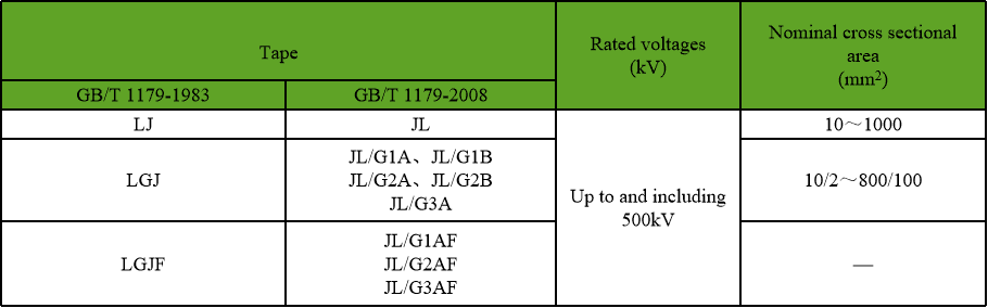
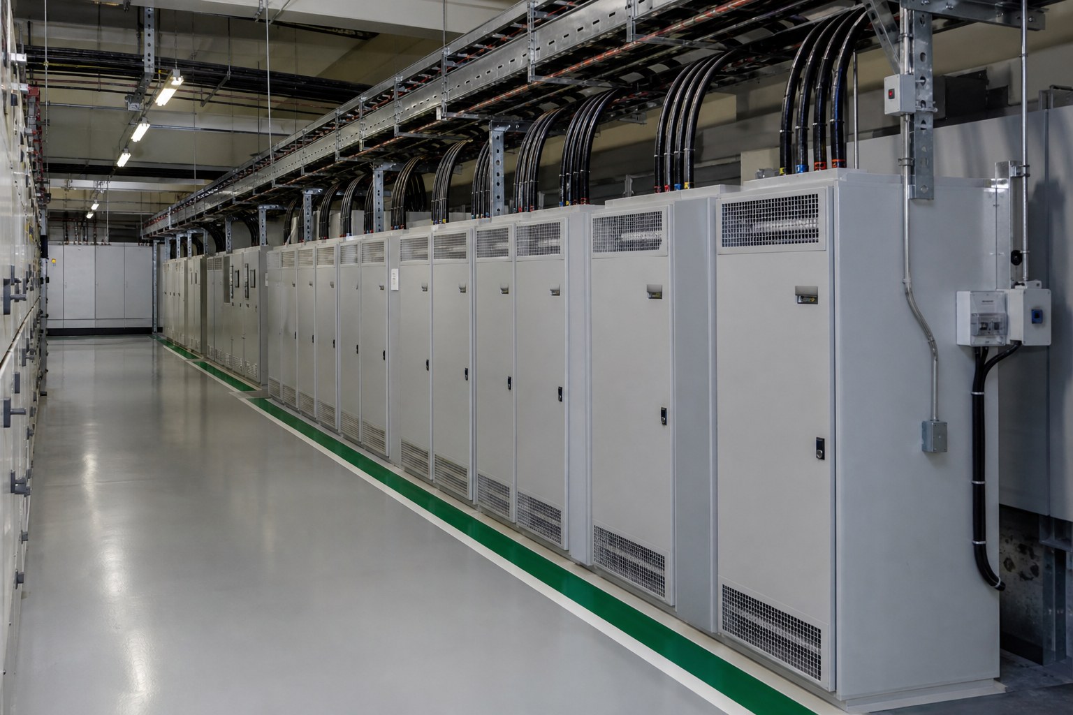
On a single-line diagram a capacitor bank is a symbol with two plates and a feeder drawn to it. In a switchroom the same arrangement is a cable running between a board and an enclosure full of reactive equipment that switches in and out all day.
That cable is often sized from the bank rating alone, on the assumption that the current is sinusoidal and steady. Both assumptions are questionable in a plant where drives, rectifiers and other non-linear loads make up much of the demand.
What follows is a practical view of the points where a capacitor bank cable is asked to do more than its label suggests, and of the questions worth settling before the order is placed.
Why Reactive Power Becomes a Capacitor Bank Cable Question
Poor power factor means the supply has to deliver more current than the useful power alone would require. Correction reduces that current upstream, which is the whole reason the equipment is installed.
Between the switchboard and the capacitor, though, the feeder carries the bank current. That current depends on the bank rating at the applied voltage, and in a real installation it also carries whatever harmonic components the network imposes on it.
The result is a feeder whose thermal duty is not obvious from the nameplate, in a circuit that is switched more often than almost any other in the building.
None of that makes the cable selection difficult. It simply means the schedule has to state the assumption about harmonics rather than leave it implied.
A capacitor bank cable operates in a circuit where the current is not a clean sine wave, so harmonic content belongs in the sizing discussion.
What the Feeder Between Board and Capacitor Carries
Four components of current belong in the conversation, and only the first appears on a simple rating calculation.
- The fundamental current corresponding to the bank rating at the applied voltage.
- Harmonic current drawn or supplied by the bank in the presence of network distortion.
- Switching transients each time the bank is energised or the steps change over.
- Any circulating current arising from the arrangement of steps and reactors in the same enclosure.
A capacitor bank cable sized on the first item alone is a cable sized on the easiest part of its duty.
Power factor correction equipment is often added after the plant has changed, which means the cable has to be considered against the harmonics already present.
Conventional and Detuned Compensation Compared
The two arrangements behave differently in a distorted network, and the difference reaches the cable.
| Aspect | Conventional bank | Detuned bank |
|---|---|---|
| Reactor | None in series with the capacitor | Reactor in series with each capacitor step |
| Behaviour at harmonic frequencies | Can amplify distortion if tuned to a resonant point | Shifts the resonant point below the dominant harmonic |
| Current seen by the feeder | Mainly fundamental, plus network harmonics | Fundamental plus harmonics with reactor loading |
| Typical selection driver | Plant with low distortion | Plant with drives, rectifiers or arc loads |
Neither column is better in the abstract. The network decides which arrangement is appropriate, and the cable follows that decision.
A detuned reactor changes the current the feeder sees as well as the frequency response of the bank, so the two are inseparable for cable purposes.
Harmonic Current and Conductor Selection
Conductor size is chosen against a current and a temperature rise. When the current contains harmonics, the root mean square value rises, and skin and proximity effects change the effective resistance at those frequencies.
For a feeder to reactive equipment the practical consequence is that derating factors belong in the calculation, and they should be stated with the assumption that produced them.
The neutral and any protective conductor are worth a separate look, since triplen harmonics behave differently in three-phase systems and can produce more current in the neutral than a straightforward balanced load would suggest.
Where the bank is installed in stages, the feeder may be sized for the final total while the initial stage is smaller. That is sensible, provided the record makes clear which stage the cable was selected for and what the intermediate current will be.
Harmonic current raises conductor temperature for the same fundamental current, and that effect is easy to miss on a schedule drawn up for the 50 or 60 Hz component.
Protection, Switching and Earthing Practice
Five points that decide whether the feeder behaves in service as it did in the study.
Protection that tolerates harmonic content
Devices chosen on fundamental current alone can misoperate when the waveform is distorted.
Switching frequency and duty
A bank that steps in and out repeatedly imposes a cycling duty on both the cable and its terminations.
Discharge and isolation arrangements
Stored energy has to be managed before anyone works on the circuit, and that belongs in the switching procedure.
Earthing of the enclosure and the feeder
The protective conductor arrangement should be settled with the supply system, not inferred from the drawing.
Termination suited to the conductor
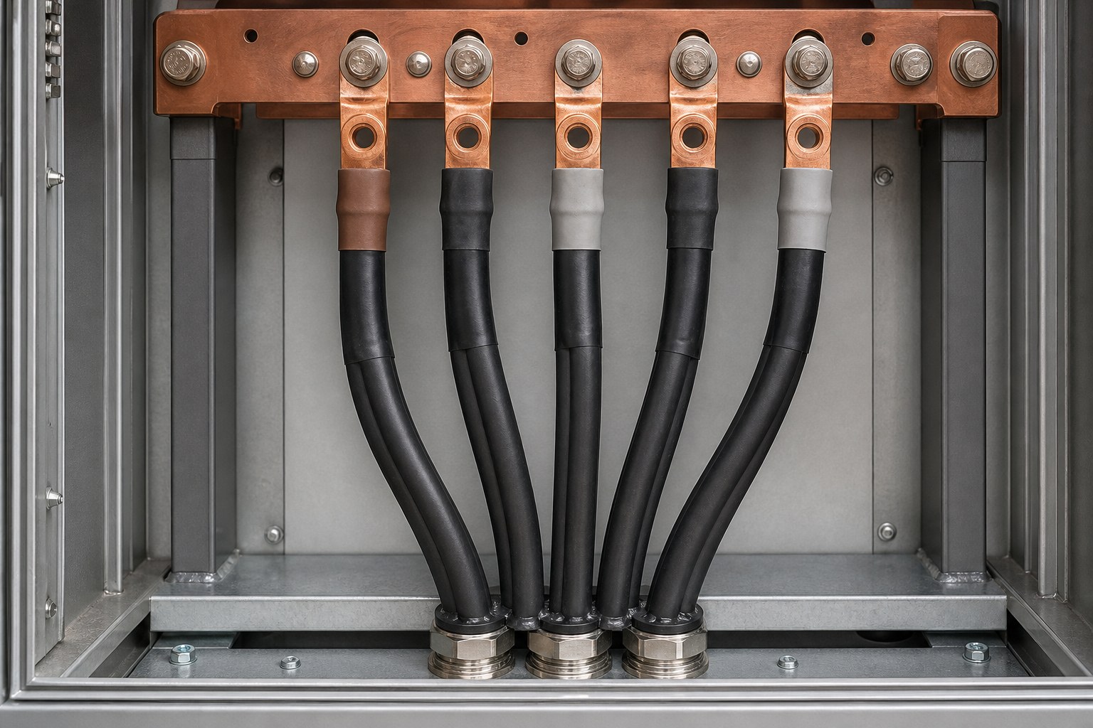
Reactive equipment is often connected with large or flexible conductors, and the lug or gland must match what is being terminated.
Reactive compensation is a load that switches frequently, and frequent switching is what aging does to insulation and to the connections at each end.
Ambient and Enclosure Conditions Around Capacitors
Reactive equipment sits in some of the warmest places in a plant, and the cable shares that environment.
| Condition | Why it matters to the feeder | What to confirm |
|---|---|---|
| High ambient temperature | Reduces the current the cable can carry for the same cross section | Design ambient for the switchroom, not the outdoor average |
| Grouped or bundled routing | Raises local temperature and derates each circuit | Number of circuits sharing the tray or duct |
| Enclosure ventilation | Hot air around a bank is warmer than the room average | Ventilation arrangement and any temperature rise stated by the bank supplier |
| Route length from the board | Affects voltage rise as well as current | Actual route length rather than a scaled estimate |
These are the figures that turn a nominal current into a cable cross section, and they come from the plant rather than from a catalogue.
A Bank That Was Moved Twice
Situation: A plant added drives to a process line over three years and then installed a capacitor bank to bring the power factor back within the level the supply agreement assumed. The bank was placed where spare switchboard space existed rather than where the reactive load was.
Finding: The first position put the bank on a long feeder and close to a section of the network where distortion was already high. The installation worked, and the current measured at the board was noticeably higher than the figure in the original calculation.
Decision: The bank was relocated nearer the load and the feeder was re-selected with the measured harmonic content stated in the brief rather than assumed. The steps were also re-arranged so that the operating pattern changed less often.
Result: Measured current at the board came closer to the design figure and switching events fell. The cable in the second position was ordered against data rather than an assumption, which is the part worth repeating.
Capacitor Bank Cable Routing Between the Board and the Bank
Route length matters twice in this circuit. It affects the voltage at the bank, and it affects the impedance between the supply and the capacitors, which is one of the parameters that sets how the installation responds to harmonics.
Short, direct routes are usually preferable for reasons of cost and voltage, and they also reduce the chance of the feeder sharing a tray with circuits that inject distortion of their own.
Where the cable has to travel through a plant, the route should be recorded with its actual length. A calculation that used a scaled drawing measurement is a calculation with an unknown error in it.
Commissioning Checks Before the Bank Is Energised
Five checks that catch most of the problems while the site is still quiet.
- Confirm the feeder is the cable that was selected, with the rating and derating assumptions on the record.
- Check terminations at both ends for conductor preparation, torque and strain relief.
- Verify the protective conductor and enclosure earthing before any switching takes place.
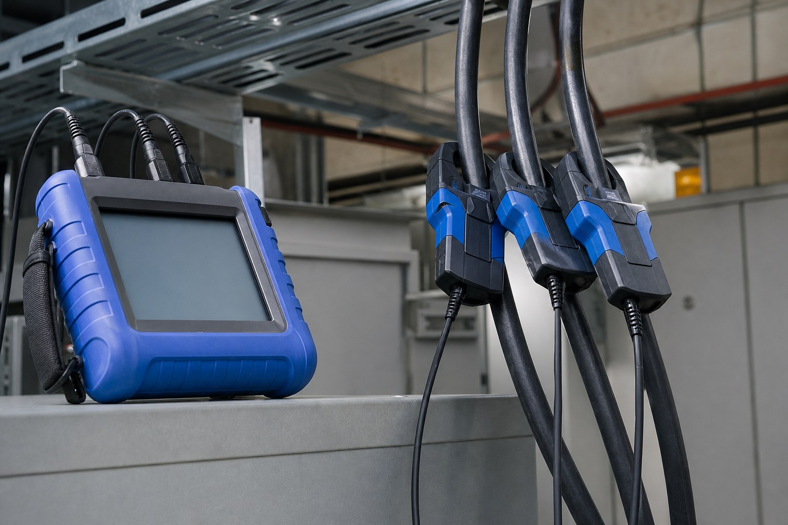
- Record the current and voltage at the board with the bank in service and out of service.
- Note the ambient temperature in the enclosure at the time of the readings, so the figures can be interpreted later.
Commissioning records from a quiet site are far more useful than measurements taken during a disturbed day two years later.
Capacitor Bank Cable Maintenance and Ageing
The parts of a reactive installation that suffer most are the connections and the equipment that switches. Cable insulation ages with temperature, and a feeder running warmer than intended ages faster than its nominal life suggests.
A planned routine that includes thermographic inspection of terminations, a check of enclosure temperature and a review of the switching pattern will find most developing faults early.
When the plant changes again, and it usually does, the records from the first installation are what allow the bank and its feeder to be reassessed quickly. The question at that point is not what the cable is, but what duty it has actually been seeing.
RFQ Details for a Capacitor Bank Cable
These details let the capacitor bank cable be selected against the network it will actually see, rather than against the bank rating alone.
- bank rating in steps, with the applied voltage and connection arrangement
- whether reactors are included and how the steps are tuned
- measured or anticipated harmonic content at the connection point
- design ambient temperature inside the enclosure or switchroom
- route length from the board to the bank, drawn rather than scaled
- how often the steps switch during a normal operating day
- supply system earthing arrangement and protective conductor requirement
- the terminations in use at both ends and the conductor type expected
Technical references such as IEC 60502, IEC 60228 and IEC 60332 can align cable construction and test terminology. The approved project specification, applicable local rules and qualified design authority still govern the final system decision.
JINCHUAN Cable Support for power factor correction installations
JINCHUAN Cable manufactures power cable for circuits where the current is not a clean sine wave, and can supply conductors and insulation data for a feeder feeding reactive equipment.
Review the power cable range and the manufacturing profile, then send the bank details and the measured network conditions so the feeder can be matched to them.
Read About JINCHUAN Cable or Contact JINCHUAN Cable with the project voltage, route and service conditions.
Fix the bank arrangement and the measured distortion before the feeder is ordered, because a cable chosen for a clean sinusoidal current is being asked to do a different job.
FAQ
Does a capacitor bank cable need a larger conductor than the rating implies?
It often does, because harmonic current adds to the fundamental and raises conductor temperature for the same useful power.
What is a detuned reactor for?
It shifts the resonance of the bank below the dominant harmonic, which keeps the installation from amplifying distortion already present on the network.
Why does the feeder length matter here?
It affects the voltage at the bank and the impedance between supply and capacitors, both of which influence how the installation behaves.
Is frequent switching a problem for cable?
Repeated energisation cycles work the cable terminations and insulation, so switching duty belongs in the specification discussion.
Should the neutral be treated differently?
In three-phase systems with triplen harmonics the neutral can carry more current than a balanced fundamental load would suggest, so it is worth checking separately.
What ambient temperature should be used?
The temperature inside the enclosure or switchroom where the cable runs, which is usually higher than the outdoor design figure.
How is earthing handled?
The protective conductor arrangement follows the supply system earthing method, and it should be confirmed with the electrical designer rather than assumed.
Can the bank be installed in stages?
Yes, and the feeder is often sized for the final total. The record should state which stage the selection was based on.
What should commissioning record?
Current and voltage at the board with the bank in and out of service, plus the ambient temperature at the time of the readings.
How does JINCHUAN Cable support this kind of project?
JINCHUAN Cable supplies the power cable and provides conductor and insulation data so the feeder can be checked against the real duty.