
A buried cable and an overhead line protect themselves in completely different ways. One relies on a continuous earthed screen and a solid dielectric; the other relies on air, distance and insulators that can flash over and recover.
Where the two meet, the mismatch is exposed. An incoming wave from the overhead line reaches the point where the route goes underground, finds a cable that cannot flash over and recover, and concentrates its energy exactly where the change happens.
That is why the transition point attracts surge arresters, careful earthing and a good deal of attention during design, even on routes where nothing else is treated as special.

Why the Junction Needs a Surge Arrester
A travelling wave is a moving disturbance along a conductor, and it deals with whatever it finds by dividing its energy between what continues along the line and what reflects back from the discontinuity.
A change from overhead conductor to a buried cable is a significant discontinuity. The surge impedance of the two routes differ, and the wave behaves accordingly, with the resulting voltage at the changeover depending on the balance between them.
The overhead line absorbs an overvoltage event with relative ease. A flashover on an insulator is visible, self clearing and repairable. The buried cable has no such option: its insulation is solid, and any breakdown is permanent.
The transition, by being part of both worlds and belonging fully to neither, ends up carrying the worst of the exposure without the self protecting behaviour of the overhead side.
A surge arrester at a transition limits the voltage that reaches the cable by diverting the energy of an incoming wave to earth before the insulation has to withstand it.
What a Transition Point Needs
Five items are usually present on a well designed changeover between overhead and cable.
A defined protective level
The impulse voltage the cable end has to withstand has to be stated, because it is the figure the coordinated arrangement is built around.
An arrester with a matching duty
Rated voltage, energy and continuous operating requirements all follow from the network and the earthing, not from a catalogue default.
A short, direct connection to earth
The lead between the arrester and its earth connection carries a high frequency current and adds voltage, so its length matters.
An earth electrode with a known figure
The earth resistance at the transition is part of the protection, and a design that does not state it cannot be verified.
A cable end that can take the stress
Termination details, screen bonding and sheath voltage limitation at the cable end all belong to the same calculation.
Insulation coordination is the exercise of choosing the arrester, the cable insulation and the earthing so each level sits in the right order under the same event.
Two Kinds of Exposure
The two routes fail in different ways, and the differences explain why the changeover needs its own design.
| Aspect | Overhead route | Buried cable |
|---|---|---|
| Response to overvoltage | Insulator may flash over and recover | Solid insulation suffers permanent damage |
| Earthing | Distributed along the route through poles | Bonded screen with defined points |
| Access for repair | Usually straightforward | Excavation, and often at the worst time of year |
| Diagnosis after an event | Often visible | Usually requires testing and, eventually, excavation |
A failure at the changeover therefore tends to be expensive out of proportion to its physical size.
A travelling wave arrives along the overhead line, reaches the transition, and reflects or continues according to what it meets, which is why the geometry of the joint between the two routes matters so much.
Where a Surge Arrester Installation Goes Wrong
The recurring faults at changeover points are rarely subtle.
- An arrester fitted at the pole with a long earth lead running down and away from the cable end.
- A cable terminated without any sheath voltage limitation at the end of a long screen.
- A bond between the screen and the earth electrode forgotten when the pit was backfilled.
- A transition pole added or moved during construction without the coordinate check being repeated.
- An earth electrode installed but never measured, leaving the design figure unverified.
Each of these is a connection rather than a component, which is why the detail drawing matters more than the equipment list.
The transition pole carries the change of route and often the arrester as well, so its earthing and its access have to be designed together with the cable.
A Pole Top Surge Arrester and a Long Earth Lead
Situation: A rural feeder had an arrester mounted high on the transition pole, with an earth lead running several metres down the pole to an electrode beside the cable pit.
Finding: The arrangement looked correct on the single line diagram and the components were correctly rated. The lead length, however, added voltage during a fast event, so the cable end saw more stress than the coordination exercise had assumed.
Decision: The arrester was relocated closer to the cable termination, the earth connection was shortened and bonded directly to the cable screen at the transition, and the electrode was measured and recorded.
Result: The revised arrangement matched the assumption behind the insulation figure, and the change was cheap because it was hardware and geometry rather than a different cable.
Earth resistance at the arrester is part of the protection rather than a detail to be measured afterwards, because its value determines the voltage that the insulation sees.
Placement Options for the Surge Arrester
Where the device sits changes what the cable end experiences.
| Placement | Effect on protection | Practical consequence |
|---|---|---|
| At the transition pole, close to the cable end | Shortest protective path for the cable | Needs mounting height and access for replacement |
| Further along the overhead line | Leaves part of the route between device and cable | Cheaper to reach, less effective for the cable |
| Inside the substation only | Protects the equipment, not the transition | Common cause of cable end failures on long feeders |
The first option is not always possible, and where it is not, the distance to the protected point has to enter the calculation rather than be ignored.
Earthing the Surge Arrester
An arrester performs by conducting, and what it conducts has to reach earth by the shortest practical route. Every metre of lead adds inductance, and every added inductance adds voltage while the current is flowing.
That voltage is subtracted from the protective margin the insulation was designed around, which is why the length and routing of the earth connection is treated as part of the design rather than as an installation preference.
At the transition, the screen of the cable and the earth electrode are part of the same path. Bonding them at the cable end keeps the two at the same potential during an event, and omitting that bond leaves the sheath insulation carrying a difference it was never sized for.
The measured earth resistance then becomes the number that closes the loop, because it is the only way to know that the arrangement as built matches the arrangement as designed.
Before the Cable Is Pulled
Four items to complete while the pit is still open and the drawings are still in play.
Confirm the protective level in writing
The figure the design assumes should be recorded, so a later change of arrester can be checked against it.
Settle the earth electrode position
It has to be reachable, outside the trafficked area and compatible with the cable route leaving the pit.
Agree the screen bonding at the end
Whether the screen is bonded, and how, is settled before the termination is prepared.
Photograph the arrangement
Before backfill, a photograph with the earth connection visible is worth more than a paragraph written from memory afterwards.
What Goes in the Record
The records at a transition are short and disproportionately valuable.
- Arrester type, rating and the batch or serial reference.
- The measured earth resistance and the date it was measured.
- The bonding arrangement at the cable end, with a photograph.
- The position of the transition relative to the route drawings.
- Any change made during construction, and the reason for it.
This is enough to reconstruct what protects the cable without opening the pit.
What the Supplier Can and Cannot Decide
The cable manufacturer can state the impulse level the insulation is designed to withstand and the mechanical limits of the end being terminated. Those two figures feed directly into the coordination exercise.
The manufacturer cannot decide where the surge arrester sits, how long its earth lead is or what earth resistance the site will achieve. Those belong to the network design and to the civil work around the pole.
Where the two are brought together at enquiry stage, the project leaves with a cable whose stated withstand level matches the protection being installed.
Where they are not, the transition is commissioned with two independently reasonable decisions and no calculation connecting them, which is how a well built cable fails in its first storm season.
RFQ Inputs for Transition Protection
These points let the cable end, the surge arrester and the earthing around them be checked against each other before the joint is made.
- the impulse withstand level the transition is designed for
- the arrester type, rating and expected placement
- the length and route of the earth connection from the device
- the target earth resistance and how it will be verified
- the screen bonding and sheath voltage arrangement at the cable end
- the cable construction at the termination, including the screen
- the terminal and equipment that the cable end connects to
- the test records and photographs the owner expects at handover
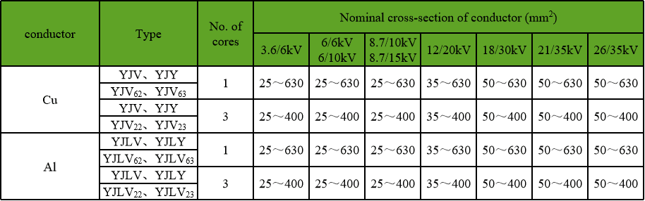
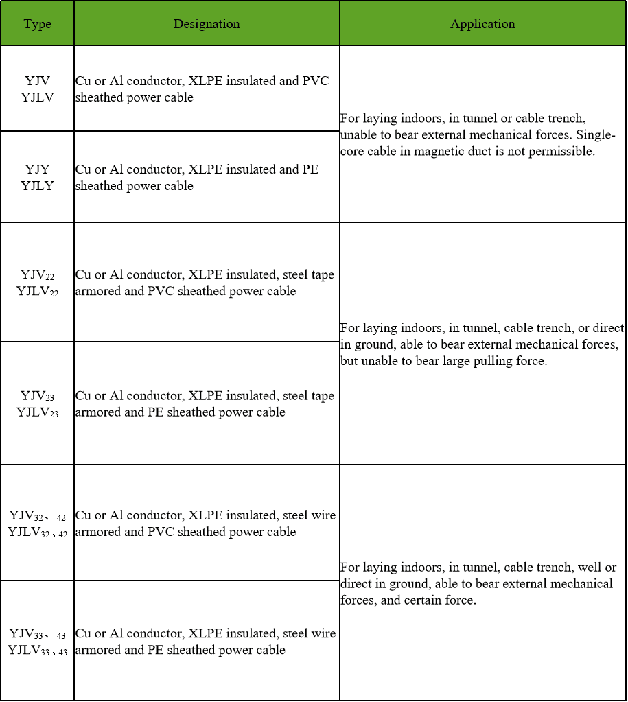
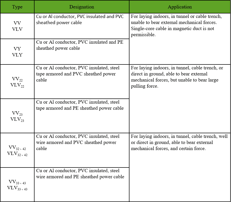
Technical references such as IEC 60502, IEC 60228 and IEC 60332 can align cable construction and test terminology. The approved project specification, applicable local rules and qualified design authority still govern the final system decision.
JINCHUAN Cable Support for overhead to underground transitions
JINCHUAN Cable supplies cable with the insulation and screen details an insulation coordination exercise depends on, and can confirm the withstand figures that apply to the construction ordered.
Review the cable range and the manufacturing profile, then bring the transition details into the same discussion as the cable end.
Agree the surge arrester arrangement before the termination is prepared, because the cable end and the protection above it have to be sized against each other.
FAQ
Why is a transition point treated separately?
It joins two routes with different surge impedance and different tolerance of overvoltage, so it sees a concentration of stress that neither route experiences alone.
What does a surge arrester do?
It conducts when the voltage exceeds its threshold and diverts the energy to earth, which limits the voltage that reaches the cable end.
What is insulation coordination?
It is the process of choosing the arrester, the insulation levels and the earthing so that each withstands the same event in the right order.
Does the earth lead length matter?
It does. The lead has inductance, so a longer connection adds voltage during the event and reduces the margin available to the cable.
Should the cable screen be bonded at the transition?
In most arrangements the screen is bonded to the earth electrode at the cable end, so both sides rise together during an event rather than the sheath insulation carrying the difference.
How is the design verified?
By measuring earth resistance at the installation, recording the arrangement and comparing it against the assumptions used in the coordination exercise.
Can the cable be changed to reduce the risk?
Within limits. The insulation level of the cable ordered is one input, but placement, earthing and connection length usually decide the outcome.
Where should the arrester be mounted?
As close to the cable end as the pole allows, so the protective path is short and the cable termination sees the limited voltage.
What records should be kept?
Arrester type and rating, measured earth resistance, bonding arrangement with a photograph, and any change made during construction.
How can JINCHUAN Cable support a transition design?
JINCHUAN Cable can confirm the insulation withstand and screen details of the construction supplied, which are the cable side of the coordination calculation.