
A cable hanging down a shaft carries its own weight before it carries electrical current. That simple fact is often hidden when a vertical riser is priced from horizontal tray details. Vertical power cable support must transfer weight into the building at planned levels, control movement, protect the sheath and preserve access to joints, fire barriers and terminations.
The right support is not necessarily the most clamps. A long run can need a combination of load-bearing cleats, intermediate guides, bend restraints, seismic or movement allowance and local protection at floor penetrations. The arrangement follows cable mass, free length, shaft geometry, environment and the approved structural design.
This guide helps buyers compare a complete riser package. It covers route evidence, support calculations, hardware interfaces, installation sequence, fire-stopping, inspection and the information a supplier needs before manufacturing or packing a vertical cable system.
The First Support Took the Weight of the Whole Shaft
Situation: A high-rise plant extension receives several feeder cables through a narrow electrical riser. The installation crew places clamps near the upper entry because the drawing shows a continuous shaft with no intermediate support schedule.
Finding: The upper clamp and its substrate are carrying more cable weight than the original detail assumed. Lower sections also rub against a tray edge when the building moves slightly, and a fire barrier leaves no room to inspect the cable after sealing.
Decision: The design team divides the riser into load-transfer zones, verifies substrate and fixing capacity, adds guided and load-bearing supports, and coordinates penetration seals with access requirements before the next pull.
Result: The revised arrangement gives each support a defined job, preserves the cable sheath and produces a record that can be checked during future inspection or replacement.
Design vertical power cable support around weight transfer, movement, access and the actual riser geometry rather than clamp count alone.
Walk the Shaft Before Choosing the Hardware
Vertical support decisions are controlled by details that a general route length does not reveal.
Measure the free-hanging length
Record floor-to-floor levels, offsets, bends, joint positions and any section that changes from supported to suspended. These dimensions form the starting point for load transfer and access review.
Identify the building substrate
Concrete, steel, blockwork and proprietary riser systems accept different anchors and loads. Structural approval should cover the actual fixing location, edge distance and installation sequence.
Mark movement and vibration sources
Thermal movement, rotating equipment, seismic design, elevator shafts and maintenance traffic can move a cable or its support. State where movement is expected and which restraint remains flexible.
Reserve inspection space
A support can be strong yet impossible to inspect if it sits behind a sealed barrier or crowded equipment. Leave access for fasteners, cable surface checks and replacement planning.
The vertical power cable support review should connect every support zone with cable identity, fixing detail and the responsible structural owner.
Riser Inputs That Change Support Selection
Use a section register so the supplier and structural reviewer work from the same vertical route facts.
| Input | What to record | Evidence before release |
|---|---|---|
| Cable load | Construction, finished mass, number of circuits and free length | Approved datasheet and riser schedule |
| Support zone | Level, elevation, load-bearing or guiding function and spacing basis | Support layout with section identity |
| Fixing substrate | Concrete, steel, wall system, anchor type and access | Structural detail and approved fixing |
| Movement case | Thermal, vibration, seismic or building movement assumptions | Design note and restraint detail |
| Penetration | Sleeve, fire barrier, water path, bend and inspection access | Coordinated penetration drawing |
| Maintenance | Removal path, spare access, labels and safe work area | Maintenance review and handover record |
A support schedule becomes auditable when each level can be traced to a cable group, fixing detail and responsible approval.
A vertical power cable support calculation must consider the cable construction, free length, bends, cleats, joints and fire-barrier interfaces.
Separate Load-Bearing Supports From Guides
Vertical power cable support has more than one mechanical function. A load-bearing cleat or bracket transfers weight into the structure; a guide keeps the cable aligned; a restraint limits movement at a bend or entry. Treating every item as the same clamp can hide where the actual load is carried and make the installation difficult to inspect.
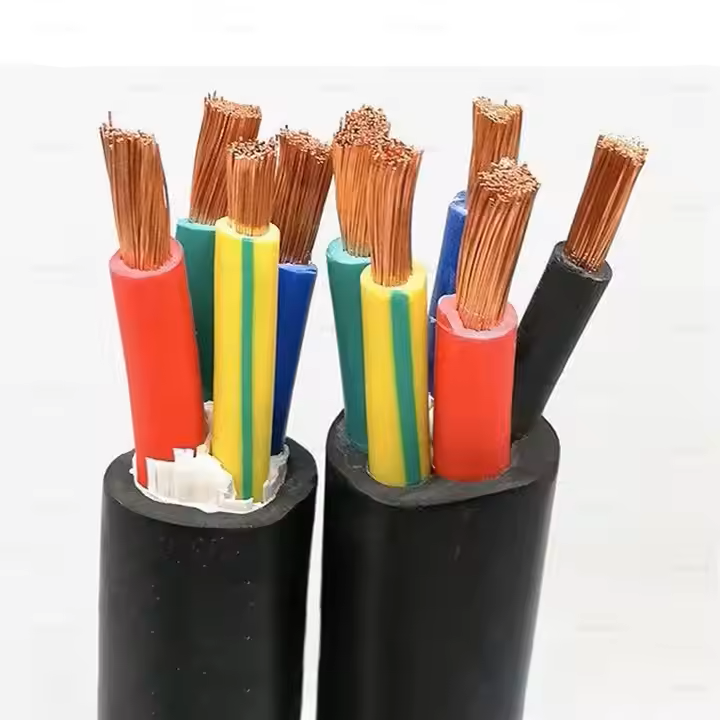
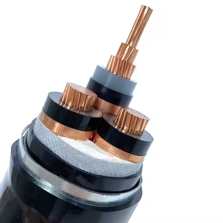
The cable construction also affects the arrangement. Outer diameter, armor, sheath, minimum bend radius, allowable compression and the presence of joints or terminations govern how the support contacts the cable. The accessory schedule should identify those interfaces rather than referring only to a nominal cable size.
Where several circuits share a shaft, keep phase, feeder and support identities together. Maintenance teams need to know which support can be released, which cable must remain restrained and whether removing one circuit changes the load on neighboring hardware.
Treat vertical power cable support as a maintainable system with inspection points, replacement access and records that survive later building work.
Common Riser Details That Fail in Service
The following shortcuts can pass an early drawing review and still create a difficult installation or maintenance condition.
- A horizontal tray spacing detail is copied into a vertical shaft without a weight-transfer calculation.
- The support is selected by cable diameter while finished mass, sheath pressure and armor contact are not reviewed.
- A penetration is fire-stopped before support and inspection positions are confirmed.
- The top and bottom bends are left to field improvisation because only straight runs appear on the support schedule.
- Temporary pulling supports remain in place without an approved permanent restraint or removal record.
- Labels identify the panel but not the riser section, making later access work slower and riskier.
A strong detail explains what happens at levels, bends, entries and barriers, not just along the straight shaft.
Include vertical power cable support hardware, installation labor, testing and as-built evidence in the quotation scope.
Compare Three Vertical Installation Arrangements
Select an arrangement against cable mass, shaft geometry, movement and maintenance consequence.
| Arrangement | Typical use | Main advantage | Control to confirm |
|---|---|---|---|
| Continuous cleated riser | Short or moderately tall runs with regular structure | Simple identity and access | Load transfer, fixing capacity and bend restraint |
| Sectioned riser with load platforms | Long shafts or heavy multi-circuit groups | Weight is shared by planned levels | Platform structure, fire interfaces and joint access |
| Guided riser with flexible movement zones | Vibration, thermal or building movement | Controls alignment without locking every section | Movement range, sheath pressure and inspection |
| Jointed vertical route | Access or drum limits require intermediate joints | Reduces handling length | Joint support, environment, testing and service clearance |
The lowest hardware count is not automatically the simplest lifecycle arrangement. Compare installation, inspection and replacement work as one package.
Release the Shaft in Four Inspection Gates
A vertical route becomes difficult to correct after floors are closed or barriers are sealed, so hold points should occur while the work remains visible.
Gate 1: substrate and anchors
Verify the support location, fixing type, edge distance, torque or installation method and structural release before cable loading.
Gate 2: empty support alignment
Check levels, spacing, bend paths, access and penetration coordination with the supports installed but before the cable obscures them.
Gate 3: cable seating and restraint
Confirm contact, radius, compression, labels, movement allowances and the absence of sheath damage after each section is positioned.
Gate 4: barrier and handover
Inspect fire or water seals, retain photos and section identities, and close the as-built record before access is restricted.
A Fire Seal Closed the Only Inspection Gap
Situation: A contractor seals a floor penetration immediately after pulling the cable to protect the construction schedule. The final support drawing is issued later and places a load-bearing cleat above the sealed opening.
Finding: The cleat can be installed, but its fasteners cannot be inspected or replaced without disturbing the barrier. The cable label is also hidden behind the seal, so future maintenance cannot identify the section from the accessible side.
Decision: The team reopens the coordination detail, moves the support to an accessible zone, updates the fire-stop interface and records the barrier product, installer and inspection date with the cable identity.
Result: Fire performance and mechanical support are both documented, and maintenance can verify the arrangement without dismantling a protected penetration.
What the Riser Handover File Should Contain
The finished route should be understandable to a technician who was not present during the original pull.
- Riser elevation, section names, cable and feeder identities, joint levels and termination endpoints.
- Support schedule showing load-bearing, guiding and movement-control functions by level.
- Anchor, bracket, cleat, shroud, sleeve and fire-stop product references with installation records.
- Photos before cable placement, after restraint and before barrier closure, each linked to a section.
- Inspection, torque, test, deviation and repair records that identify the responsible reviewer.
- Maintenance constraints, spare access, safe work limits and the change-control path for future cables.
A complete handover file turns a hidden shaft into a route that can be inspected, extended or repaired with less discovery work.
Price the Complete Riser Workfront
A comparable quotation should show more than the cable and a line for clamps. It should identify supports, anchors, brackets, bend restraints, penetrations, fire or water barriers, lifting, access equipment, installation supervision and records. Otherwise a bidder may price a horizontal-style pull while another includes the work needed to make a vertical route safe and maintainable.
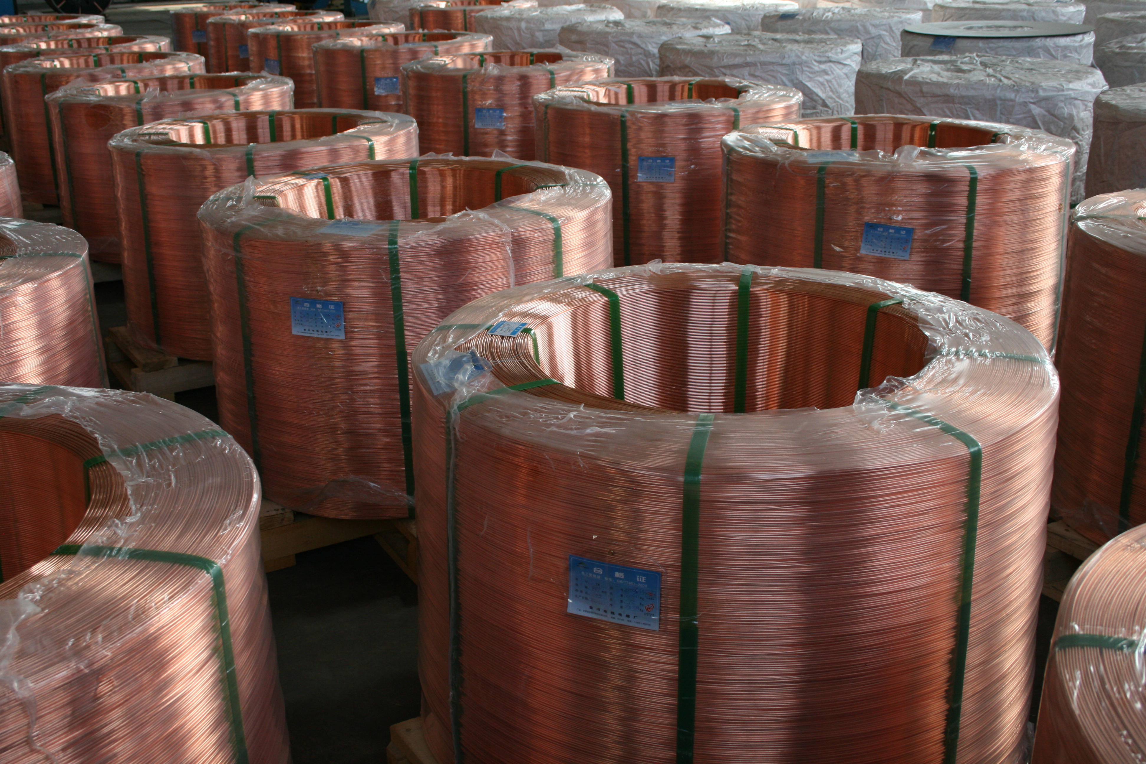
Drum planning also changes in a riser. Long lengths reduce joints but increase lifting and payout demands; shorter lengths simplify handling but add joint bays, accessories and tests. The buyer should provide the approved route and installation method before asking for a final drum schedule.
JINCHUAN Cable can clarify product construction, finished dimensions, mass and drum identity. The building structure, support design, fire strategy and site installation remain with qualified project teams, so the RFQ should keep those boundaries visible.
RFQ Inputs for a Vertical Riser Cable Package
Send the cable schedule together with the shaft and support information needed for a buildable quotation. Confirm vertical power cable support in the RFQ.
- riser elevation, floor levels, section lengths and access restrictions
- cable construction, finished diameter, mass, bend radius and quantity
- support functions, spacing basis, anchor substrates and structural approvals
- movement, vibration, seismic, thermal and mechanical exposure assumptions
- penetration, fire-stop, water-seal and inspection requirements
- drum lengths, lifting, pulling equipment, workfront stages and permits
- labels, photos, test records, deviations and as-built document format
- spares, maintenance access and future route reservations
Technical references such as IEC 60502, IEC 60228 and IEC 60332 can align cable construction and test terminology. The approved project specification, applicable local rules and qualified design authority still govern the final system decision.
JINCHUAN Cable Support for vertical power cable risers and shafts
JINCHUAN Cable can provide construction data, finished dimensions, mass, drum identity and agreed factory records for a vertical cable package. Those inputs help the buyer coordinate the product with the shaft, supports, penetrations and installation sequence approved by the project team.
Review JINCHUAN Cable product categories and the company profile, then send the riser schedule and support basis for an item-specific quotation.
Freeze the riser geometry, load-transfer zones, penetration detail and inspection gates before manufacturing lengths or support hardware are released. Keep vertical power cable support in the release record.
FAQ
Why does a vertical cable need a separate support design?
A vertical run transfers cable weight into the building and can experience movement, bend loading and access constraints that are not represented by a horizontal tray detail.
Is cleat spacing the same as in a horizontal tray?
Not automatically. The spacing and support function follow cable mass, free length, fixing capacity, movement, fault forces and the approved mechanical design.
What is the difference between a load-bearing support and a guide?
A load-bearing support transfers weight to the structure. A guide controls alignment or movement. The schedule should show which function each item performs.
What should be checked before fire-stopping a riser?
Confirm support, bend, label, access, seal product and inspection positions first. Sealing should not hide an unverified mechanical interface.
Can several feeders share one riser support system?
They can when loading, spacing, movement, fault forces, access and future removal are included in the approved design.
Should a vertical riser use one continuous drum length?
That depends on lifting, payout, access, joint strategy and maintenance. A longer length reduces joints but may create a difficult workfront.
What product information should come from the cable supplier?
Request construction, finished dimensions, mass, bend radius, drum identity, applicable tests and handling information for the ordered cable.
Who approves the riser anchors and structure?
The responsible structural and electrical project authorities should approve the fixing and support design for the actual building and installation method.
Which standards can support the cable discussion?
IEC cable references can align product and conductor terminology, while the approved structural, fire, installation and project rules govern the riser.
How can JINCHUAN Cable support a riser inquiry?
JINCHUAN Cable can clarify product data, dimensions, mass, drums and factory records so the buyer's qualified team can complete support and installation approval.