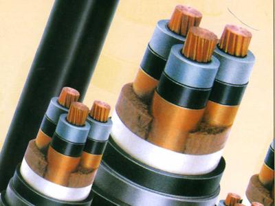

A thermal camera turns a switchroom into a picture of where the current is working hardest, and terminations are usually where it shows first.
Infrared thermography is the name for a survey built on that idea: compare similar parts of a live installation, measure the difference, and decide which of them has changed for the worse.
The camera is the easy part. The value comes from the load on the circuit that day, the conditions in the room, and whether anybody kept a record of what the last round looked like.
What the Camera Is Actually Measuring
A camera measures radiated energy and reports it as an apparent temperature. Anything that changes how much energy reaches the lens, including the surface material, reflected heat and the air in between, changes the number it gives back.
That is why the useful output is a comparison rather than an absolute figure. Two phases of the same circuit, under the same load, at the same time, say far more than one reading taken on its own.
Where a surface cannot be seen directly, the survey cannot see it at all. Covers, enclosures and buried joints are blind spots, and no amount of equipment changes that.
Infrared thermography works on a loaded circuit, so a survey taken with the plant idle has very little to compare.
Where Hot Spots Show Up
Four places account for most of what an infrared thermography round finds.
- Terminations, where a loose connection or a corroded contact raises resistance.
- Joints and cable boxes, where a jointing fault or trapped moisture shows as a local rise.
- Cleats and supports on single core routes, where induced heating appears in magnetic materials.
- Tray and enclosure entries, where cables are grouped and heat from one circuit reaches another.
Each of those has a different cause, and the survey only points at the place.
A cable termination hot spot usually points at resistance rather than at load, and the useful question is what changed since the last round.
What a Useful Survey Needs
Four conditions decide whether the figures mean anything.
Load on the circuit
A temperature difference needs current behind it, so the load at the time belongs in the record beside every image.
The same conditions each time
Ambient temperature, time of day and plant state all move the readings, so the round should be repeated in comparable circumstances.
A trained operator
Emissivity settings, reflected temperature and focus all change the result, and the person holding the camera matters more than the model.
Something to compare against
A previous round, or an identical circuit in the same room, gives the reading the reference it needs.
Thermal imaging survey results are far more useful as a trend than as a single reading, which is why the same route should be surveyed the same way each time.
Reading a Result
Four patterns cover most findings.
| What you see | Likely direction | Next step |
|---|---|---|
| One phase warmer than the others | Connection resistance | Check the termination |
| Whole circuit warm, evenly | Load or ambient | Confirm the load first |
| Local hot spot at a cleat | Induced heating | Review the clamp material |
| Rise that repeats each round | Progressive change | Trend it and plan the work |
The camera says where. The pattern usually says why.
Electrical maintenance inspection schedules should place the survey where a loose connection would be expensive, rather than everywhere a camera can be pointed.
Case: A Warm Phase That Was Not a Fault
Situation: A round flagged one phase termination as warmer than the other two on a feeder, and the report recommended an immediate shutdown for inspection.
Finding: The connection was sound. The load was unbalanced that day, and the board had been surveyed in the afternoon with one side facing a glazed wall in direct sun.
Decision: The round was repeated at a comparable load and the same time of day as previous rounds, and the unbalanced load was corrected at the distribution board.
Result: The repeat showed the three phases within a few degrees of each other and the shutdown was avoided. Later rounds on that board have kept to the same conditions.
Cable joint temperature rises for more than one reason, and separating a loose termination from an overloaded circuit is what makes a result actionable.
Before You Trust a Result
Four questions separate a finding from an artefact.
Was the circuit loaded?
A warm reading with no current behind it is a measurement of the room or the sun.
Was the surface visible?
Covers, grilles and enclosures hide more than they show, and an obscured termination has not been surveyed.
Has the load changed?
A circuit carrying more than it did last time will run warmer without anything being wrong.
Does the pattern repeat?
A result that appears again under the same conditions is a finding. One that disappears was usually an artefact.
Why the Trend Matters More Than the Reading
One round produces a single figure per termination. Two rounds produce a direction, and a direction is what maintenance planning actually needs.
The same route surveyed under comparable conditions, with the load written next to each image, turns a loose connection from a surprise into a scheduled repair.
That comparison is only possible if the images and the conditions are kept together. A folder of photographs with no load figures beside them is hard to use a year later.
Where the Round Pays
Four asset types, and the cost of missing something at each.
| Asset | Typical finding | Cost of missing it |
|---|---|---|
| Feeder terminations | Loose or corroded contact | Outage and damaged equipment |
| Cable joints and boxes | Local heating from moisture | Joint failure |
| Single core cleats | Induced heating | Sheath damage |
| Distribution boards | Unbalanced or overloaded ways | Repeat failures |
Ranking the assets by the cost of missing something is the cheapest part of planning an infrared thermography round.
Where Rounds Disappoint
A survey is easy to do badly.
- Surveying at no load and reporting differences anyway.
- Comparing an afternoon round with a night round and treating the change as a trend.
- Keeping images without the load figures beside them.
- Pointing the camera at reflective surfaces and accepting the number it returns.
None of those failures is caused by the equipment.
Fitting It Into Maintenance
Infrared thermography fits best where it replaces a guess. It does not replace an insulation test, a discharge measurement, or a proper look at a joint that has already failed once.
The useful habit is a fixed round, at comparable conditions, with the results filed next to the load figures. That file becomes the baseline every later round is measured against.
On a critical feeder the survey answers a scheduling question rather than a yes or no question, which is exactly what an operations team needs from it.
RFQ Inputs for Condition Monitoring
These details let the cable be specified with the monitoring regime in mind.
- the circuits that will be surveyed and how critical each one is
- the load profile of those circuits through the year
- whether terminations are indoor or exposed
- the enclosure types, and whether covers can be opened for a round
- the sheath and screen arrangement on single core routes
- the joint and termination types in use
- the baseline conditions the operator intends to repeat
- the records that have to be kept with each round
Technical references such as IEC 60502, IEC 60228 and IEC 60332 can align cable construction and test terminology. The approved project specification, applicable local rules and qualified design authority still govern the final system decision.
JINCHUAN Cable Support for condition monitoring of terminations, joints and supports
JINCHUAN Cable supplies the construction and termination details that an infrared thermography round depends on, including sheath arrangement, cleat interfaces and joint types.
Review the cable range and the manufacturing profile, then send the survey plan so the construction and the accessories suit it.
Fix the conditions before the first round, and infrared thermography becomes a trend instead of a photograph.
FAQ
What does infrared thermography find on a cable system?
It shows where a live installation runs warmer than its surroundings, which usually points at resistance, load or induced heating.
Does the plant have to be running?
Yes. A round with no load has almost nothing to compare, because the heat a fault produces comes from the current flowing.
Can it see inside a joint or a buried cable?
No. The camera only sees surfaces it can look at directly, so covered, enclosed and buried parts are outside it.
Why compare phases rather than use a fixed figure?
Surface material, reflection and ambient conditions all shift the reading, so a comparison between identical parts under the same load is far more reliable.
How often should a round be repeated?
Often enough to build a trend under comparable conditions, and the interval usually follows how critical the circuit is.
What should go in the record?
The image, the load at the time, the ambient temperature and the location, so the next round has something to compare against.
Can a warm termination have a harmless cause?
Yes. An unbalanced load, reflected sunlight or a hot day can all raise a reading without anything being wrong with the connection.
Where does the survey pay best?
At terminations, joints and single core routes, where a missed problem leads to an outage rather than to a nuisance.
Does it replace an insulation test?
No. It answers a different question, and the two are usually used together on critical circuits.
How can JINCHUAN Cable help with a monitoring plan?
JINCHUAN Cable can supply the construction and interface details a round relies on, and confirm what the cable includes.